Sep 12, 2014
lolachampcar That sounds reasonable. Turn on all bleed resistors in a given module to divert some of the current around all of the individual cell groups in the module. This would affectively divert current around the whole module allowing other modules to catch up.�
Sep 12, 2014
wk057 I'm not sure how out of balance the cells get from one another... but even with all 6 sets of bleed resistors enabled on a module through an 8 hour charge we're talkkng about 20Wh dissipated which is pretty negligible.
For simplicity it probably only does balancing at high states of charge so the differences are more accurate.
There is almost certainly no circuitry for inter-module charge shuffling here considering the presence of the isolation chip.�
Sep 12, 2014
tom66 If you charged at the same rate as balancing, you could effectively bypass a module. However this would be only be available at very low charge currents (like at the end of a charge cycle.)
This might be why Tesla use specific 158 ohm, 1% resistors, as knowing cell voltage, they would know cell balance current accurately.�
Sep 12, 2014
scaesare Magnet, I've asked earlier for some source for earlier claims, but didn't see a reply.
Thus far, it doesn't appear that anything in wk057's documented tear down support these ideas. Is this conjecture on your part? If not, what is the source for your assertions?
Thanks.�
Sep 12, 2014
spaceballs I've fixed my own BMB (a few times) in my Roadster, Model S pictures posted here just seems to refine the existing tech, Magnet posts regarding "active balance" and "active impedance" etc.. seem like conjecture to me.�
Sep 12, 2014
scaesare It feels that way to me too, I'd just like to clarify (and keep the thread constructive).�
Sep 12, 2014
tom66 Do you have any pictures of your BMB? It'd be interesting to compare it.�
Sep 12, 2014
glhs272 I am trying to understand what I am seeing here. Are the individual module BMS boards entirely capsulated within the module? Meaning they operate entirely one their own within the module requiring no communication or connection to the other modules or the rest of the car for that matter. Thus each module is self balancing within itself? Is this correct or am I not seeing the interconnection between the other modules to the main BMS board?�
Sep 12, 2014
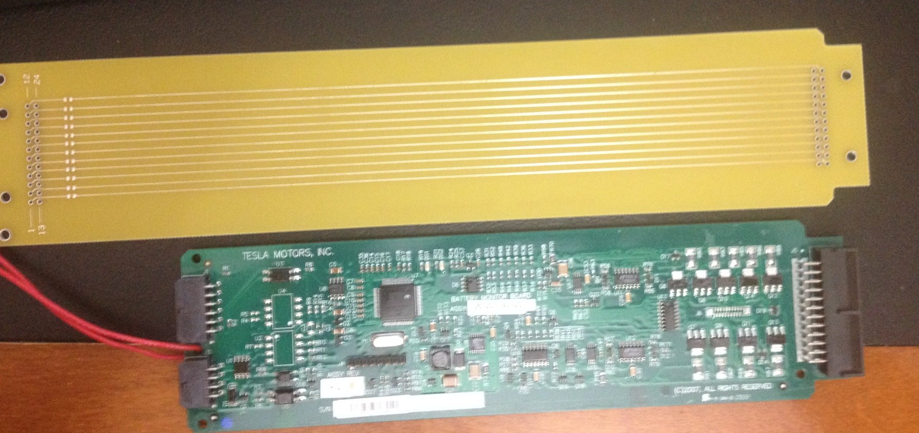
spaceballs Here is a fuzzy pic from an old email, the better ones at home. Has same fuses (mine are on the back of the PCB), similar bleed resistor logic, CAN bus transceiver isolator. Though looks like they removed the on-board dc-dc converter, and removed two of the temperature sensors.
- - - Updated - - -
What your seeing is BMB boards, they talk to the BMS.
They operate on their own, but talk to each other over CAN bus and to the the BMS.
If it's anything like the Roaster, it will only self balance when the BMS tells the BMB it to bleed off certain bricks down to lower the other cells to balance it. Normally the BMB just reports back voltages to the BMS.
Your not seeing the interconnections.�
Sep 12, 2014
tom66 The particular IC on the Model S BMB is autonomous so to speak. The BMS will not command it to sink currently directly, but the BMS will set a target voltage and it will bleed off to reach that target.�
Sep 12, 2014
magnet Yes. Each BMB on each module has it's own target balance voltage (TVB) for each string in the module, but each BMB also sends it's highest TBV value to the BMS which then resets the global highest TBV of all the modules. Shuttling is a bad way to describe what is going on. You could call it "lossless balancing" or "lossless equalization" or "distribution balancing"
It is not totally lossless of course as the BMB is powered by the module. Now what happens if you "charge/distribute" through the balance wires and that "charger/distribute-r" is powered by the battery itself. The total module voltage would be decreased but you would redistribute the charge to balance each string.�
Sep 12, 2014
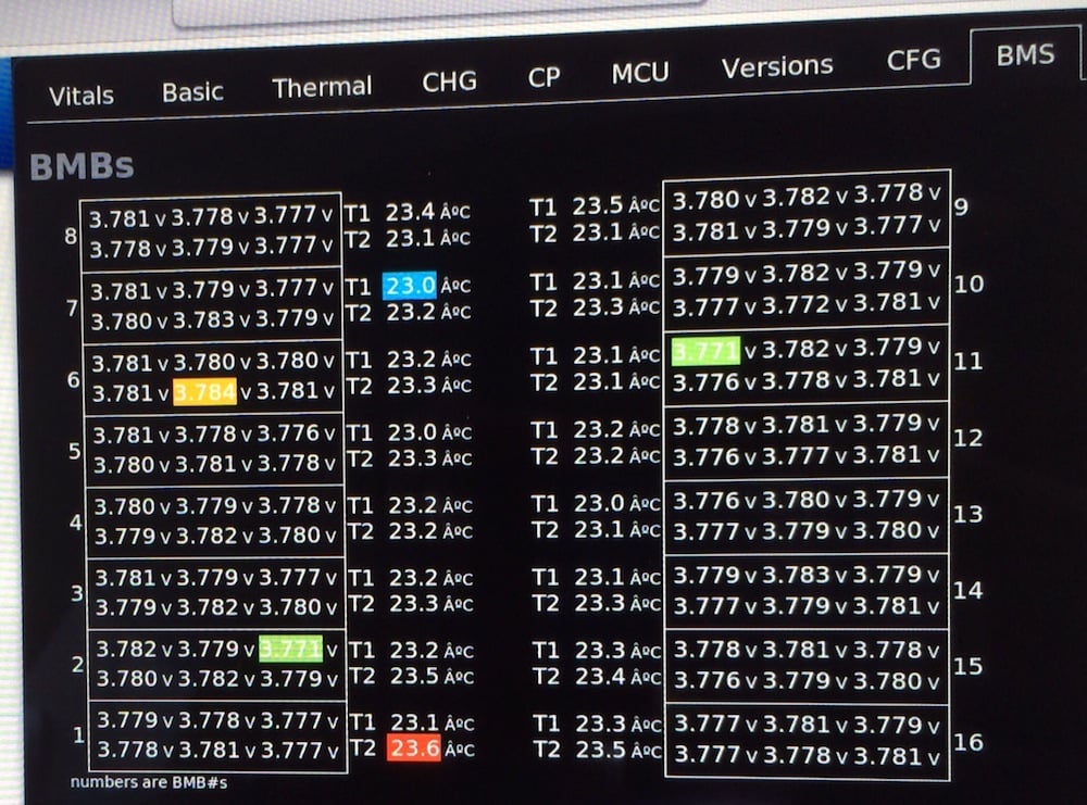
Cottonwood Below is a diagnostic screen available to Tesla service people that shows the Voltage and Temperature measurements from the BMBs. Notice high and low Voltages and Temperatures being highlighted. Also notice how tight the range is with a Voltage spread of 0.013 Volts and a Temperature spread of 0.6? C. The car had been charging at 19 kW for at least 20 minutes at this point after the tech fixed my HPWC.
 �
�
Sep 12, 2014
glhs272 Thanks spaceballs and tom66 for the clarifications. Boy it would be nice to have access to the screens in Cottonwood's pic.�
Sep 12, 2014
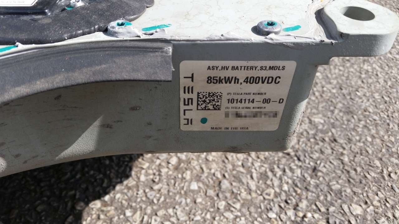
TiGWolf FYI
Next time you blur out your S/N, you might want to do the same to the Datamatrix code.. Because it says your serial number is ST13L0027159
 �
�

Sep 12, 2014
RubberToe This thread is now being followed and linked to by CleanTechnica:
Disassembling The Tesla Model S Battery Pack | CleanTechnica
The buzz is starting to build, not Kardashian level yet, but ramping up :biggrin:�
Sep 12, 2014
SirNick At least part of what he's saying makes sense, given the circuitry on the per-module management boards:
Think of it this way.. From the negative terminal of the entire pack to the positive terminal, there are sixteen modules, and let's say 400V for a nice round number. From the per-module BMB's perspective, there are negative (0v) and positive (~25v) ends. If you count from the pack negative, through module A, then module B, and so on until you reach the positive terminal, module A's negative is the pack negative, and mod A's positive is mod B's negative, and so on, in series. Clear?
Sorry, I know this is basic and well-understood, but bear with me. It's critical that everyone is up to speed on this much to make sense of what's next.
So, each BMB (per module) can bleed a group (a group of parallel cells) to equalize it with its (series) neighbors. It does this by shorting out that group's positive and negative ends (a difference of ~4v) through the bleeder resistor for that group. When you do this, you have at most 158R / 4 (paralleled resistance) = 39.5R draining the group's voltage down to where the BMB wants it to be. Still clear?
OK, now think about what happens when the pack is charging. If the bleeder resistors are turned on by the FET, instead of bleeding power out of the group, you are effectively limiting the ability for that group to charge. Not completely, the cells will still receive some of the charge current, but not as much as if the cells in the group were the only electrical path through. Remember, the charge is current-limited, so by shunting around a group, you take the available current and divide it through two paths -- one through the group, one around it. This limits the voltage available to that specific group while the others still receive their full "dose". This isn't "shuttling" of charge from one group or module to another, but it is a way to control how much each group/module charges.
Furthermore, the FET can either be turned on hard, or activated in its linear region, depending on whether the BMB's signal to the FET's gate is digital logic or analog. What this means is that the FET itself can be anything between a dead short (or close to it -- the Rds(on) spec), and open circuit. With a DAC feeding the gate, you could variably control the impedance through that bleeder circuit (fixed resistors in series with the variable FET resistance), for any one cell group, and ultimately for the entire module. This enables active control over the amount of charge of any cell group in the entire pack. Ergo, that "active impedance" thing someone spoke of earlier. Pretty clever.�
Sep 12, 2014
rabar10 This is still passive balancing, and is not loss-less -- the extra energy is lost via heat in those shunting resistors.
It IS intelligent balancing, i.e. per-paralleled-cell-group inside each module, and then among all modules in the pack. But the system is not actively removing energy from one module/cell in the pack and placing that energy into another cell/module.
When any of those shunt FETs are on, a current will flow proportional to that paralleled-cell-group's voltage. That current will either come from the cells themselves (when not being charged), or from externally-supplied current i.e. if the pack is being charged.
Tesla has chosen to carefully match and balance cells/modules before they are integrated into the pack. That way the circuitry required to keep those cells/modules in balance, over the life of the pack, is minimized.
The up-sides of avoiding active balancing are both decreased component cost and also fewer failure-modes -- fewer places where a component failure can cause bad things to happen (like internal shorts or larger continuous drains on a cell group).
The down-side is that the entire pack is always limited by its weakest paralleled cell group capacity. There's no way to prop up one weak group (via active balancing) to access any additional Ahrs available in the stronger groups. Not an issue if your QC is good and your faith in all the cells to perform/degrade similarly over time is high.
Active cooling also helps a lot here -- since these cells' performance/degradation is so temperature-dependent, ensuring that everything is as near the same temperature as possible helps a lot.�
Sep 12, 2014
Cottonwood And remember the resistive bleed circuits are pretty delicate in their load. The 4 158 Ohm resistors in parallel are 39.5 Ohms with the cell Voltage about 4 Volts, that means the bleed current is about 0.1 Amp, dissipating about 0.4 Watts. The Amp-hour capacity of these packs is about 85 kWh / 370 Volts or about 230 Amp-hours. That means that it would take 2.3 hours to bleed 0.1% off of a set of paralleled cells. That's a very delicate and gentle balance that only works in a reasonable time, if the cells are almost matched to start with.�
Sep 12, 2014
tom66 I drew up this quick schematic to get an idea of what the balancing circuit looks like. There's a diode as well, but it appears to only be used for reverse protection/transients. (Might be a zener.) It's obvious that conducted noise was a concern to Tesla - I suppose when you're pulling 1000A from a battery at maybe 30kHz, there's going to be a little noise! So they appear to have a network of filters, starting with L7 and C24, and the network of 11.3k + C26/C27, and 10k + C56/C57.
Also of note is that Tesla follow good engineering guidelines for ceramic capacitors in "mission critical" systems. A short of any of the capacitors attached to the battery cell would lead to a pack contactor abort, so they put two capacitors in series. One capacitor is probably sufficient to achieve the desired attenuation at the frequency of operation so the battery pack can operate with one capacitor bad in each series group just fine. They also fuse both the positive and negative of the pack despite this not being strictly necessary (you would only need to fuse the positive.)�
Sep 12, 2014
magnet Yes! You get it! This the "active impedance" control is only enabled towards end of charge when the charge is slowing the the string voltage is more stable. Is it totally lossless? No of course not. But is is safer than true shuttling and it is more efficient than simple bleed balancing.�
Sep 12, 2014
spaceballs This is just a lighter form of charge shunting, here are that different types of cell equalization for your reference Cell Balancing and Battery Equalisation
This is no way like you said earlier that it's "lossless balancing" or "lossless equalization". No matter how you crunch the numbers energy is converted to heat when the power darlington transistor is active, either during the charge or after the charge.�
Sep 12, 2014
spaceballs Thanks for the quick schematic!
I really wish they put in the the network of filters orginally on the roadster BMB, as without it I kept blowing fuses due do an large inductive spike when you connect up ESS service disconnect. Though my case was unique, but that suggested to me that the existing design was already somewhat near the edge of requiring one.�
Sep 12, 2014
wk057 There is a main BMS board in the rear of the pack, I just haven't gotten any good pictures of it yet.
Pack housing is heading to the scrap yard tomorrow now that it's down to the bare aluminum and I have no use for it.
I suppose the rest of this belongs in my other thread, but, figure I'll summarize my progress here.
I worked on very temporary setup for my lower voltage battery configuration (44.4V) where 8 sets of 2 modules are in series with each other (so 8 sets at 44.4V) and all of those hooked in parallel. I used 4/0 wiring and lugs to do a nice equal-length-to-load wiring of the setup to balance the current draw and it seems to work. I made sure the path from negative to positive through the load from any module is through the same total length of wire. (I'll probably post a pic in my other thread). I reused the main pack fuse for now, and an aftermarket 1000A/75mV shunt.
The best part is that I finally powered something off of the pack! .... a box fan! .... through a 48V->12V DC-DC converter and a 12V->120V inverter. My 48V 8kW inverter arrives Monday.�
Sep 12, 2014
scaesare Is this anything other than simply enabling the bleed resistors during he charge cycle for the higher SOC cells?
As you say, there's no "shuttling" of charge from one cell to another... it's simply dissipating a portion of the charge current being delivered to a given cell group...�
Sep 12, 2014
magnet that is simply what you think. it is not that simple. it in effect increases the voltage to bricks not only reduces. and it balances module voltage as the bmb uses power. more balancing uses more power. there is no such thing as lossless
balancing of course but that is what this schemes are since
is use so little. current like water takes the path of least resistance. bleed balancing is totally lossy�
Sep 13, 2014
tom66 I don't think this IC can vary the shunt current. It's either all or nothing.
At the end of the charge cycle for balancing, to bring the cells up, current can be set to approx 100mA, and the shunts can be turned on.
However in my mind it would make more sense to set current to zero and instead bleed off all high cells.�
Sep 13, 2014
JRP3 I wonder if you could get more for it selling it back to Tesla? Nothing wrong with it, right?�
Sep 13, 2014
tom66 I'm sure Tesla has strict supply chain controls, so they can't take back scrap unless they have a full chain of paperwork showing where it's been and that it's the genuine article.�
Sep 13, 2014
JRP3 I suppose you are correct, though it does have a serial number and a code on it.�
Sep 13, 2014
Johan If you have room, keep it. You're one of the very first to go DIY on a MS pack but in the future many will follow. You'll able to sell this thing for $500-1000 I figure.�
Sep 13, 2014
spaceballs You might be correct.
Now that I'm able to get an roaster working with my custom brick, maybe if I took it up a notch an got a whole Model S pack working with custom batteries. Anyone got a spare Model S I can experiment on? :biggrin:�
Sep 13, 2014
wk057 Do you think you could get more energy density into a Model S pack than Tesla already does safely? If so... Careers | Tesla Motors
But seriously, that seems like a pretty cool project. With the Model S, it looks pretty straight forward honestly, aside from the liquid cooling aspect. Just make bricks of a similar configuration, hook the BMS sense leads to the right spots, and it should work fine I would think, technically speaking.
- - - Updated - - -
Actually, I was looking at the modules and, they're pretty tightly packed. However, I think there is a little room for improvement, but not much. Given substantial effort I bet 2-3% more cells in there... but the cost would certainly outweigh the ~9 mile range improvement.�
Sep 13, 2014
JRP3 What do you think about Tesla fitting their new GF format cells into the same housing, is there room for a 5mm taller cell?�
Sep 13, 2014
spaceballs LOL I don't think Tesla would offer me enough to move me and family to CA.
Actually I could if that was an requirement spec, I would maximized energy density wise with raw cells submerged in fluid (high dielectric value). This would remove the large amount of metal coolant lines interwoven between the cells, I would keep the the cells rupture C metal can imprint, and wire fuse though.
Agreed looks straight forward. I wonder how many people would want only an 75 mile pack, but loose over 50% of the battery weight? Wonder how fast 0-60 it would go then :biggrin:�
Sep 13, 2014
TonyWilliams I will pay far above scrap price for the battery case and cover, to be used as an education aid.
Tony�
Sep 13, 2014
magnet Look I said it was not truly lossless but if you want to know more about this type of balance schemes those are the keywords. Even true shuttling is not truly losses. What Tesla has done is approach lossless balancing without resorting to real shuttling. If it was simply lighter use of the bleed resistors Tesla would not be granted a patent. There is one more trick to using "excess energy" to make it even more efficient
None if this really matters for off grid use though. If you keep the batteries in an air conditioned room they will not even need liquid cooling or the BMS/BMB. One other benefit to using many small cells in parallel is it allows Tesla to sort and then pair all the cells into a brick such that all bricks are extremely well balanced to begin with. The only reason they would ever go out of balance is if some cells were running at a different temperature than others. This can happen with a coolant loop even with good distribution so Tesla does need a BMS. If you use air cooling in an air conditioned room and lay the pack flat you wont need a BMS at all. Bulk charging should be fine. Put the battery in a separate room lined with concrete/brick/whatever just in case. I mean off the grid pack is probably going to last a few days so the discharge rate with be really low compared to the Model S�
Sep 13, 2014
magnet Great question") �
�
Sep 13, 2014
tom66 One thing you could tell us is, was Elon telling the truth when he said it's 1/4" aluminium? Because that is very thick. Also, you could see what can puncture it, though that may require specialist equipment.�
Sep 13, 2014
wk057 Pack housing is gone already
I did actually measure the aluminum bottom prior and it was slightly more than 1/4" thick.
Edit: Just found out that the pack housing weighed in at right around 250 lbs. (Including the bulk of the aluminum module mounting bars that I couldn't reuse, and the couple pieces of aluminum tubing from the coolant loop in the front)�
Sep 13, 2014
tom66 So about 20% of the battery weight is housing, only? Pretty heavy...! I'm sure with some changes to Model III's body (perhaps making the battery more integral to the crash structure than on Model S) could reduce this further.�
Sep 13, 2014
hcsharp I'm curious, what else was in the bottom of the housing such as insulation and/or ballistic material? It seems like the pack cools down pretty quick in the winter when exposed to cold weather.�
Sep 13, 2014
spaceballs Sounds about the same for the Roadster.�
Sep 13, 2014
wk057 There are some sheets of fireproofing material under and on top of each module. No insulation really. From the bottom of the pack up: 1/4" Aluminum, thin fire proofing sheet, plastic module cover, cell module. So, I think it will slip to whatever the external temp is pretty quickly.�
Sep 13, 2014
Cottonwood Put your buddy in touch with Tony. Tony will get his keepsake and your buddy will make more money.�
Sep 13, 2014
wk057 Yeah, tried that as soon as I read the post, but he got rid of it already... :-\
I could get the info for wherever he took it in case its in one piece still if you want, Tony...
--
Note: I was able to decode the tiny little data matrix on the one cell I snapped a shot of: 5221DACP0143000B
I assume its a serial number for the individual cell?

- - - Updated - - -
Tony:
This is the place that it was taken at today: http://www.matteo-iron.com/
He said they probably wont move it until Monday, so, might be worth contacting them if you really want it.�
Sep 13, 2014
TonyWilliams Thanks for the info. I see they are paying $0.55 to $0.65 for scrap AL.�
Sep 13, 2014
spaceballs More people noticeing this thread, now on hackaday
Tesla Model S Battery Teardown�
Sep 13, 2014
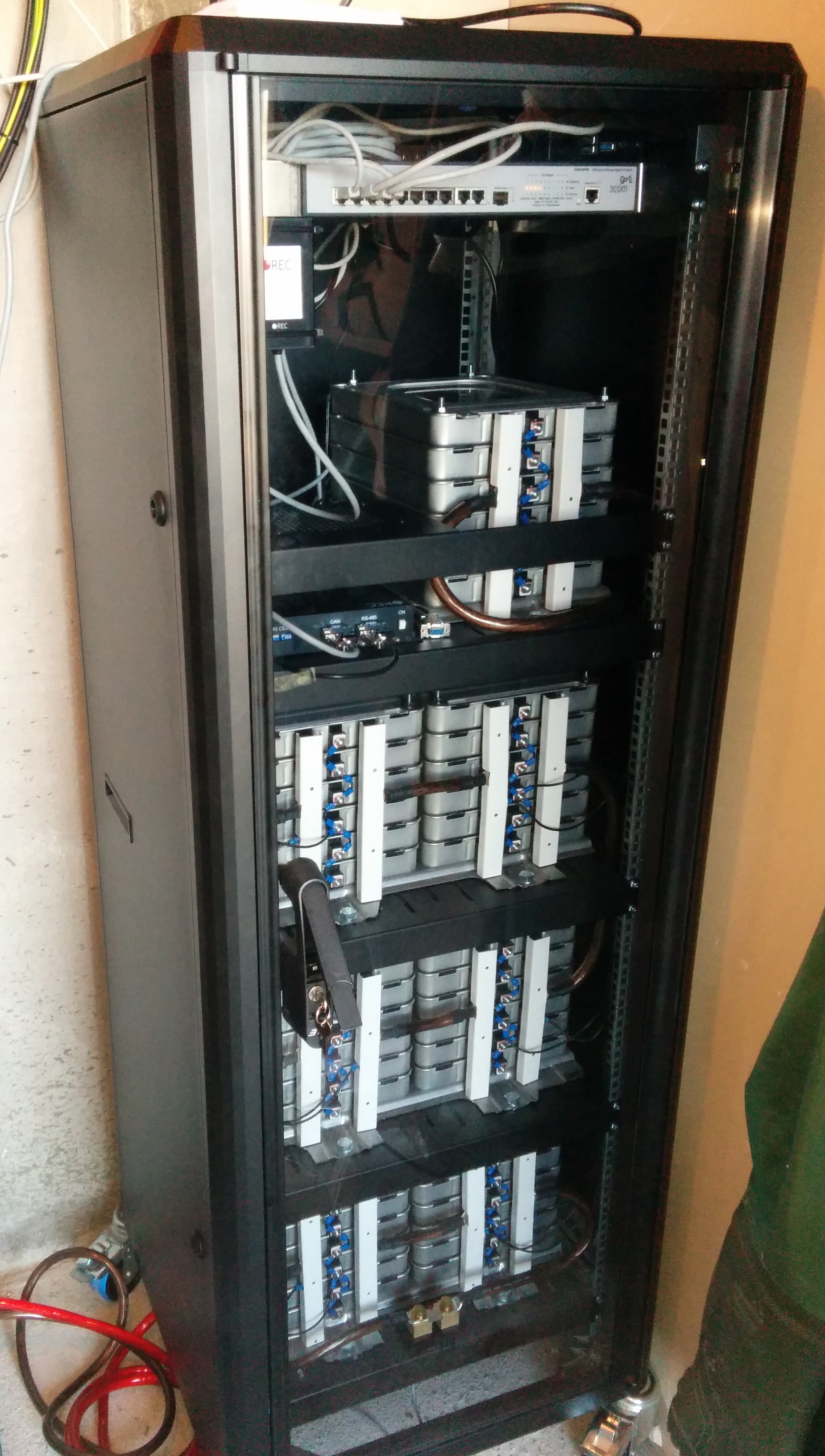
offpist I did something similar to a Nissan LEaf battery.
It is now running as an storage solution to my on-grid system.
The BMS i use is this one.
REC d.o.o.
IT has CAN support to the SMA Sunny Island 6.0H.
 �
�
Sep 14, 2014
tga Can you post more info about the system? How is everything wired, etc?�
Sep 14, 2014
magnet I think the pack come close to doubling the torsional rigidity of the Model S chassis when installed in the vehicle
So it is not dead weight like most other EV packs. Also remember it has been designed for robotic swapping and to serve as a ballistic shield.�
Sep 14, 2014
Cottonwood I have an on/off-grid system in Pagosa with SMA Sunny Islands paired with SMA Sunny Boys and conventional Lead Acid energy storage. The Sunny Island product is a well-engineered, reliable product, and works well with the Sunny Boy Solar Inverters to make an "island" off grid system, or a grid-tied system that can "island" itself and continue running when the grid goes away.
If all you want is backup power, a propane generator with an underground propane tank is much cheaper, even if you are doing grid-tied solar.�
Sep 14, 2014
drees He has a more pics and details on the MNL forum: My Nissan Leaf Forum View topic - Use of Nissan Leaf battery in Solar installation.
He broke the modules into ~48V units - 7 modules in series (each module is a 2P2S config), 6 in parallel, 42 total) so that it'd work with off-the shelf off-grid hardware. Very nice setup!�
Sep 14, 2014
spaceballs Now on EVTV EVTV Friday Show - September 12, 2014 - YouTube around 40 min in.�
Sep 14, 2014
JRP3 Of course Jack just has to take a shot at everyone involved in the thread, including the OP doing the work�
Sep 15, 2014
nlc Maybe already somewhere on the topic, but the BMS have passive balancing, with very low value, just above 100mA. Very low because the capacity is above 200Ah !!�
Sep 16, 2014
kennybobby Interesting that the TI battery monitoring chip stores the threshold voltages in OTP (one-time programmable) eprom, so there is a default setting for when the balance circuit is turned on. The FETs are driven either ON or OFF, there is no adustable gate drive to cause any sort of variable impedance balancing scheme.�
Sep 16, 2014
wk057 Just testing a bit while I wait around for my inverter...
The module side of the module BMS board's isolation IC's power input pin reads 5V, so that portion of the board is active in some fashion still running off of thr module itself.
Since I'm not sure what, if anything, this is doing in my configuration I'm going to finish disconnecting the remaining boards from my modules...�
Sep 16, 2014
kennybobby It looks like each module board talks to his neighbor passing along voltage data and fault status thru a serial bus back to the main BMS board. They are powered from the modules so will draw a small bit. Guess you probably don't have time to mess around with trying to read the serial data...�
Sep 16, 2014
nlc From the datasheet : The bq76PL536A has six dedicated outputs (CB1�CB6) that can be used to control external N-FETs as part of
a cell balancing system. The implementation of appropriate algorithms is controlled by the system host. The
CB_CTRL[CBAL1�6] bits control the state of each of the outputs. The outputs are copied from the bit state of the
CB_CTRL register, i.e., a 1 in this register activates the external balance FET by placing a high on the
associated pin.
Thus the balancing algorithm is done by the BMS master board (the host the datasheet talks about). The host sends the state it wants for these output through the SPI bus.
Because of the very low balancing current (~100mA with the four 158r in parallel), maybe they implemented a better balancing algorithm than just activate the balancing when the cell reach its maximum voltage.�
Sep 16, 2014
lolachampcar nlc,
I suspect there is a micro on each module's dedicated BMS board that handles the TI chip. It should be possible for the micro to PWM the outputs but that seems like an awful lot of work for very little gain.
WRT all the BMS boards, there has to be some type of level independent serial bus such that modules referenced at different voltages can all hang out and talk to the main board (422???). The distances and different voltage references rule out a lot of busses.�
Sep 16, 2014
wk057 The wire that connects the BMS modules together is quite literally a loop. It appears that the boards need to be all connected to make the chain continuous, also, since half of the connector connects to the previous board and half connects to the next.
I'll see if I can't get a picture of this later.�
Sep 16, 2014
Cottonwood I'm guessing optically isolated serial buses.
That would make it easy for each BMB to hang out at its own module's Voltages and still provide and easy interconnect.
- - - Updated - - -
Take a look at what the loop connectors go to on the BMB's. I bet that there are optical isolation devices there.�
Sep 16, 2014
nlc I think they don't daisy chain the TI SPI bus throuht all 16 modules to the master board. SPI bus is a sensitive and high speed bus, not really good for long wiring.
They probably interfaced the BMS modules through a microcontroler, which manage the SPI communication with the TI chip on one side, and communicate with the master board with another kind of bus which can support long distance, as RS485 for example.
At the left of the TI chip there is a 20 pin QFN chip, I can read SIL FS30A, seems to be a Silicon Lab microcontroller FS53x serie.
Pin 16 and pin 17 go the the isolator chip. These pins are P0.4/TX and P0.RX
Thus they communicate through an usart link, thus it's probably RS485 or something like that.
It means all board module are probably in parallel, and the BMS master board communicate to each module with an addressing
- - - Updated - - -
wk057 : you said the wiring go to each module like this 1 --> 2 --> 3 --> 4, etc....
Can you look with the multimeter if wire entering a board are the same signal that wire output which go to the next BMS module ?�
Sep 16, 2014
yobigd20 you know, I've seen a few recent Tesla patents publicly published that might help you out. dunno if they were available prior to last month:
Patent application title: FLEXIBLE PRINTED CIRCUIT AS HIGH VOLTAGE INTERCONNECT IN BATTERY MODULES
A System and method for improving on conventional techniques for connecting energy storage elements of a high-voltage battery pack. A tuned flexible printed circuit individually coupled to each electrode of each cell of a matrix of cells of the battery pack provides improved manufacturability and reliability.
details: FLEXIBLE PRINTED CIRCUIT AS HIGH VOLTAGE INTERCONNECT IN BATTERY MODULES - Patent application
Patent application title: POWER ELECTRONICS INTERCONNECTION FOR ELECTRIC MOTOR DRIVES
The bus bar includes a first bus bar layer formed of a first generally uniform thickness of a first bus bar conductor; a first dielectric layer overlying a top surface of the first bus bar layer; and a second bus bar layer formed of a second generally uniform thickness of a second bus bar conductor overlying a top surface of the first dielectric layer and the top surface of the first bus bar layer wherein: the first bus bar layer includes a first via for receipt of a first electrical lead of an electrical component and a second via for receipt of a second electrical lead of the electrical component and wherein: the first dielectric layer and the second bus bar layer each include a via aligned with the first via wherein the first electrical lead is extendable from beneath the first bus bar layer through the first dielectric layer and through the second bus bar layer.
details: POWER ELECTRONICS INTERCONNECTION FOR ELECTRIC MOTOR DRIVES - Patent application
lots more patents: TESLA MOTORS, INC. - Patent applications�
Sep 16, 2014
kennybobby There is no optical bus:
SPI Communications � Device to Host
Device-to-host (D2H) mode is provided on the SPI interface pins for connection to a local host microcontroller, logic, etc. D2H communications operate in voltage mode as a standard SPI interface for ease of connection to the outside world from the bq76PL536Adevice. Standard TTL-compatible logic levels are presented. All relevant SPI timing and performance parameters are met by this interface.
BMB to BMB:
Device-to-Device Vertical Bus (VBUS) Interface
Device-to-device (D2D) communications makes use of a unique, current-mode interface which provides common-mode voltage isolation between successive bq76PL536As. This vertical bus (VBUS) is found on the _N and corresponding _S pins. It provides high-speed I/O for both the SPI bus and the direct I/O pins CONV and DRDY. The current-mode interface minimizes the effects of wiring capacitance on the interface speed.
�
Sep 16, 2014
Cottonwood
Sorry for the confusion, but I did not say optical bus, I said optical isolators, or optical couplers that would be on the BMB and the BMB's would be connected by wires. See Optocoupler Tutorial and Optocoupler Application for an explanation. Here is an example of such a device that is less that $0.10 in volume and can handle 1,500 Volts of isolation: Mouser - Transistor Output Optocouplers PTR 10%, 1.5KV. These optical isolators could also be built into some of the IC's that implement higher functions on the BMB.
Optical isolators take a current to run an LED that excites a photo transistor or such, and provide Voltage isolation across that optical path. The optical isolator accepts current in and handles the common mode Voltage between BMB's. From BMB to BMB there is a maximum common mode Voltage of 25 Volts. Because the BMB's are in a circle connecting back to the BMS, there is a 400 Volt potential to jump at the end.
I would bet that at least that one, if not all, the interfaces have optical isolators to accept a current in and take care of common mode Voltage differences.�
Sep 16, 2014
kennybobby Cheers mate, i'll take that bet-- that they don't use optical isolators. Also i'll bet that the BMB cable does not make a circle loop, the top and bottom boards only connect to one other board while the inner BMBs connect to two neighbors.�
Sep 16, 2014
wk057 It actually does make a full circle...�
Sep 16, 2014
SirNick Hard to say. I don't remember where the OP said the modules connect together -- if it's the white WTB connector (J6), or the bigger black one (J1).
J6 is labeled TS1 & TS2 +/-. The traces from the connector are routed via an inner layer, and I can just make them out on the top-side scan, until they go underneath the passives near the SiLabs F530A (8051-based micro), where I lose track of them. There doesn't look to be optical isolation, though. I suspect that one wasn't the module bus, but maybe temperature sensors (hence, "TS").
But, if that is the module interconnect, then based on the peripherals listed in the micro's datasheet, it might be a LIN bus -- it's kind of the intended application. I'm not very familiar with LIN. It seems typical implementations are single-ended, level-shifted from around 12V to whatever the micro wants, internally. Unless I missed it, the datasheet doesn't specify anything beyond ~5V tolerance, and the +/- silkscreen would kind of imply differential signalling. It doesn't really add up.
Now, if the modules connect via the black connector (J1), then they go into what looks like a SiLabs 8642ED. Can't find much on that part.
From what I can see, there are four pins connected -- two at the top left and right, connected together; and two more that might be TX / RX, or a bi-directional differential pair. There are SOT (D)iodes between the connector and the uC. It looks like the trace on the second position from the top left (near the "PCBA" silkscreen) goes into one of the pins through a 4.7M resistor (R72). It looks like the other pin, near R90/C58 on the bottom right, is driven with a 4.7k resistor. The diodes could be clamps, which, combined with the high-value series resistors, could be limiting the voltage to something the uC can handle. That would make sense with differential signalling, but single-ended would be tricky without a common reference (ground) between boards. I haven't traced all the stuff, and it's a bit hard to tell where some of them go with the parts and silkscreen in the way.
- - - Updated - - -
Oh, also, based on the layout, and nearby "VBAT" silk, U2 looks like it might be a voltage regulator. If I were going to hack this board, I would probably start there.�
Sep 16, 2014
hcsharp Hah! You're both wrong! It uses newer tech than opto-isolators. It uses RF isolators. Don't worry if you hadn't heard of it before now. I hadn't either! From the isolator chip datasheet:
I don't take credit for figuring this out. The Si8642ED-B-IS chip being used was posted earlier in the thread, and somebody else even identified it as a radio-isolator, which I'd never heard of before so I read the data sheet. You learn something new every day!�
Sep 16, 2014
rabar10 Lots of good info and links to previously-identified ICs were posted earlier in-thread:
From the link posted above, the SI8642ED is an isolation chip, used between the individual BMB and the main BMS board. Each side of the chip needs its own power source. It supports passing 2 channels of high rate serial data in each direction (4-ch total).
(edit: and hcsharp beat me to it)�
Sep 16, 2014
SirNick Ohhh... I missed that. Assumed it was another micro. Oops. Man... that's esoteric stuff. Wonder why one would choose that over optical? Current draw seems low, but not super low, at ~1-5mA per channel.�
Sep 16, 2014
spaceballs btw do the LED(s) blink one about a minute? the Roadsters BMBs do (even when not connect to the CAN bus).�
Sep 17, 2014
tom66 Although the TI chips support a method of intermodule communication, Tesla does not use this interface. My guess is it's possibly because they need sufficient isolation between modules and that has none at all. Or maybe the noise immunity is not great, which is important in a safety critical system like this. It's a current mode interface.
It wouldn't be hard to figure out the interface on my opinion. I would expect the BMB and BMS to operate independently from the vehicle systems. So if you give it 12V and GND it will probably fire into life. You should then be able to see the BMS<->BMB communication on a scope. If it is RS485, many scopes will do serial decode on the data.�
Sep 24, 2014
henderrj I do love this thread � thank you wk057! I�ve read every word and searched other places and still cannot find an answer to a couple of questions. I hope you might find time to answer them for me.
You show a couple of pics of the high voltage connector (captions �Top view of the high voltage connector� and �Close up view of the external HV connector ��). Could you give me their size? I would love to know the size of the blades but I realize that information is not available to you.
The second issue is about the modules. First, I can guess the size but could you give us a more accurate measurement? Part B � Would it seem that the modules could be alternatively arranged (i.e. four each stacked in four rows)? Could they be separated (front and back of vehicle)? As I consider it the three connection types are low voltage (communication) wiring, high voltage (power) connections, and the coolant. Am I missing anything?
Again, thanks to you and all the contributors. Amazingly informative.�
Sep 24, 2014
Cottonwood From what I have learned on this thread, the 85 battery pack has 16 modules with each Module having 6x74 cells, 6 series/74 parallel. The 16 modules are connected in series to get a total of 96 cells in series, 96*74=7,104 cells/pack.
I am curious about the 60 pack.
Is it true that the 60 battery pack uses the same modules? How many modules are in series in a 60 pack?
Thanks ahead of time for the info.�
Sep 24, 2014
scaesare This very thread has some pics of the 60kWh pack and some counts of the cell totals...�
Sep 24, 2014
wk057 The female side of the HV connector has two blade slots that are almost exactly 1" wide. They go about 1.5" in, and the blade would have to be at least 1/8" thick, probably more. There is also a rod female slot that is for chassis ground that is about 1/4" diameter. There is a smaller rod connector on the HV connector that is wired with two connectors to the internal LV harness on the main PCB... presumably some kind of connection sense since if a solid rod were inserted it would close the connection.
There is a temperature sensor (wired into the internal LV harness) attached to one of the internal HV bus bars close to the HV connector.
The internal low voltage wiring harness is labeled "BIZLINK".
I don't have exact measurements on the modules, but they are approximately 28" long by 12" wide by around 3-4" tall... I'll have to measure one more accurately one of these days.
Given the dimensions of the housing, I don't see any usable alternative arrangements possible. The stock configuration would seem to make the most sense in any case. (I've rearranged the modules in a 44.4V configuration for my offgrid solar project, but that is outside of the original housing.)
There are three connectors, the HV, LV, and coolant connectors. Correct.�
Sep 25, 2014
henderrj Thank you - this is exactly what I needed.�
Sep 26, 2014
jumpjack This battery package is a maintainace nightmare: how is Tesla supposed to repair a defective battery, if it has to destroy the glued cover to access the cells?!?
There must be another method.
I also wonder if there is some redundancy in such an high complexity "part", made up of around 10.000 cells; if no redundancy is present, just one failure in 10.000 will make the whole 85 kWh battery unusable and un-repairable: a 10$ failure which leads to a 30.000$ unrecovrable failure?!?
It is just not possible.�
Sep 29, 2014
wk057 OK, so the modules, not counting the piping for the coolant loop or the small edges they rest on the sides, are 26 1/2" long and 11 1/4" wide. With the support edges they're about 12" wide. The coolant loop connectors add another ~2".�
Sep 29, 2014
JRP3 That is correct, it is not possible that a single cell failure will disable the pack.�
Sep 30, 2014
lolachampcar Thanks for the photos wk057. It is great to see inside packs like this. My colleagues and I have had a closer look at the cell monitoring PCB and made a few notes about what we could see. Apologies if this is repeating anything that has already been said:
The PCB will allows discharging of cells, or more accurately, groups of parallel cells. The charging & discharging will likely be at pack level, and any cells that are over charged can have the extra charge dissipated as heat, preventing the overall pack voltage being dictated by one rouge cell. There is also a secondary system to prevent cells going out of their safe operating region (either voltage or temperature). This is the basic premise behind EV battery management.
The board is controlled by a Silicon Labs MCU C8051F530 which looks to be powered from the monitored HV battery directly.
The host controls the 6 cell Texas Instruments BMS chip BQ76PL536A-Q1, passively balancing the cells. The BMS controls each channels 39.5? balance resistors giving 106mA discharging, just under 0.05% per hour for 74 off 2900mA cells. The BMS chip safety outputs look like they are only heading to the MCU.
The BMS ADCs are connected to the cells via inductive filtering. The cell connections are fused, although fusing isn�t consistent across the PCBs.
The host has communication to elsewhere on the vehicle across an isolation barrier that keeps the HV system separate from the LV system with two in and two out channels at 5kV isolation, with the rest of the PCB tracked with an isolation gap of what looks to be, using EN60950, roughly 400V of reinforced insulation.
The PCB testing capability seems reasonably extensive and looks to have been tested once after manufacture, suggesting a first time pass.�
Sep 30, 2014
scaesare I like to think of it in terms of hard disk technology where the device works around known acceptable failure rates.�
Sep 30, 2014
wk057 Except I think it's worth pointing out there's a significant difference: A hard disk initially maintains spare unused sectors that it can map in to use when an existing sector fails, thus "working around"" a failure. As far as we know the Tesla pack maintains no such spare capacity, however it can continue working despite a failure.
The reason why this is important is that while a disk will have enough spare sectors to remap over it's expected life thus maintaining original capacity, the Tesla pack will degrade in overall capacity with a cell failure.
By my calculations, a single cell failure results in a 1.35% loss of overall pack capacity, despite there being over 7,000 cells in the pack. (note however, that subsequent cell failures don't necessarily degrade an additional 1.35% unless it's in the same module... and with 96 modules that's much less likely).�
Sep 30, 2014
SeminoleFSU I could see the potential point of failure being the dual sided cell level fuses.
As I noted earlier in the thread there are indications that a handful of them were manually repaired at the factory prior to final assembly, meaning there certainly is not 100% success with these connections.
I did remove the protective plastic from a module to get a better look at these and, well, they're pretty weak little wires. A tiny touch moves them. However nothing can touch them inside the pack, so, they're safe from that.
My concern would be over time vibration rattling a weak one loose and causing an intermittent connection.
Not saying this is happening anywhere since I assume Tesla has accounted for this, but if there were a point of failure that would be it... 1 of 14,208 connections failing would not seem statistically improbable.�
Sep 30, 2014
scaesare I've often wondered how many points of failure exist in the battery pack using so many (thousands) of cells... I know Tesla touts having fewer moving parts, etc and therefore should be more reliable.... but....
I do realize many of those points of failures wouldn't mean an outright failure, just a diminished capacity.... but...
Since owners don't get to see the actual diagnostics on the pack to identify failed cells/connections, etc... 1.35% loss by failure of a cell here or there could easily be written of as "normal" degradation, and not a failure inside the pack.... and since the owners have no way to verify or refute- they'll just have to live with whatever Tesla decides.
Am I missing anything here?
- - - Updated - - -
Thinking out loud some more.... I wonder if Tesla's pack degradation prediction graphs, etc assume individual cell failures at certain points, or just assume all cells continue to operate normally, but just degrade?�
Sep 30, 2014
hcsharp I was just getting ready to reply to your email when your edit showed up... I'd bet you are correct. That the overall diminished pack capacity probably allows for a percentage of cell-failure-caused failure as well. I'm not sure if it's more likely that an intercoonect would fail or the cell itself would.
Given that you could lose a cell in each of the 96 modules and still only be degraded "one cell's worth" of capacity (1.35%), then as long as you don't expect to lose too many then I'm assuming it's not going to be a terribly significant factor in the overall degradation.
I'm no statistician, but (all else being equal) isn't the chance of losing 2 cells in the same pack (1/96) ^2 = 0.011% ?? (thanks to hcsharp for catching my error)�
Sep 30, 2014
scaesare No. It's .011% (all else being equal). But all else is not equal. Once you lose one cell in a brick then the other cells in that brick are stressed that much harder. The degradation from use becomes exponentially faster in that brick. With time, those other cells and fuses are more likely to fail. They will get hotter, discharged lower, and always have more current flowing through them.�
Sep 30, 2014
SeminoleFSU Ah, right you are.. my numerical answer was correct, I forgot to then recognize that percentage account's for two of those decimal points.
But I suspect those fuses are sized for to prevent thermal runaway of a battery in case of a short, massive module failure, etc... not the failure of a cell (or two or three), is such that they are going to be affected by that small of a failure.�
Sep 30, 2014
scaesare Ah this makes sense- so I wonder if their models account for that as well? I'm assuming yes- since they probably come up with the data by testing several to dozens of completely built packs, not just the individual components that comprise the pack.... *we hope*
- - - Updated - - -
The .011% number is hard for me to wrap my mind around. Does that mean over the total life of the pack? 8yrs? per year?�
Sep 30, 2014
lolachampcar This is the chance of losing two cells and having them both be in the same module of one of the 96 individual modules in the pack.
So, although a single cell loss immediately brings the entire pack capacity down by 1.35%... you could lose a cell in all the remaining 95 modules without losing any more capacity. It would take another cell loss in the same module that had already lost one previously to bring down the pack another 1.35%...
So from that standpoint, it would be at any point over the lifetime of the pack.�
Sep 30, 2014
SeminoleFSU All this talk of failures. I'm sure glad the thing has an 8 year warrantee.�
Sep 30, 2014
glhs272 Gotcha - thanks for the explanation!�
Oct 2, 2014
scaesare What could be much worse than a cell short is a bad cell that has excessive internal resistance and won't hold a charge/drains down quickly. This would bring down it's sister cells wired in parallel along with it. Not sure if the BMS would be able to compensate for this. This could possibly lead to complete pack failure if it drained down a whole group of 74 cells in parallel.�
Oct 2, 2014
glhs272 Not holding a charge would seem to be the same as a cell that failed open or had a blown fuse. That's essentially infinite resistance.
An internal short, or very low resistance would drag down the rest of the module, no?�
Oct 2, 2014
hcsharp I incorrectly worded that.
So in one scenario where a cell suddenly failed and became very low resistance or completely internally shorted, the cell would draw a lot of current from the rest of the cells in parallel and would blow the cell level fuse and take the bad cell out of the system, thus self healing more or less.
I am thinking of a cell failure mode where the cell does not sustain voltage over time as it's brothers wired in parallel do. This would be some kind of higher resistance failure in that it is not drawing as much current from it's neighbor cells, thus not blowing the fuse but draining down the pack quicker than the balancing system can compensate. A slower failure. From a pack perspective it would appear that the whole pack is not taking much of a charge anymore and the pack rapidly decays. I guess what I am trying to describe is a cascade failure. I wonder if the pack is susceptible to this?�
Oct 3, 2014
spaceballs Isn't it obvious that it is? This has been discussed previously in the Roadster threads. I think it's the Achilles heel of a Tesla battery pack. Most of our batteries will die that way - with most of the cells still in good shape and a few bricks in bad condition. For 2 years I've been trying to think of a good engineering solution to this but haven't come up with anything affordable or cheap enough.�
Oct 4, 2014
kennybobby It's obvious to people who have read into the details of this pack and the roadster pack threads. If I was Tesla the next gen pack step would be to hire custom hardware guys to build custom ASIC IC per for each cell. This IC would take existing cell monitor features (i.e. OV/OC/UV cutoffs) but add in the ability to individually "addressable" each cell (there are many ways to do this) to the ESS/BMS/BMB/whatever. So that if any brick/groups that has accelerated self-drainage it can do an binary search until the problem cell is found and disconnect it from the group (or some other technique). In the volumes that Tesla would be needing them these ASICs it would be the winner for cost. Though other side of the coin, now the problem for people like EV DIY's, is then Tesla now has an level of control (at the cell level) where even if you took the pack apart, the custom bricks/groups could still be unusable unless you software hack it, or remove the IC's.
If Tesla does go down this path make sure they keep the wire fuse! As for a prototype I built a custom roadster brick that had each cell had it's own battery monitor IC on it, everything was fine and dandy. The problem was the IC's had a feature there it would disconnect the cell from the group if more than 1.75Amp is drawn. Which at first glance doesn't seem like a problem, but it becomes one when say you have an undersized pack, and a neighbor that didn't understand "keep it under X Amps", they thought it was X miles per hour. 99% of the cells did what was predicted and disconnect them self's from the group, problem was ~2 cells didn't and all the current went through those, lucky my cells had PTC fuses on them so no cells went up in smoke.. but many of the IC didn't survive and 1-2 of them actually became shorts, so fuse is still required!�
1/1/2015
guest Sounds like interesting research, for how many cells was this done--do you have a thread or blog describing what you did and how it worked, etc.?�
Oct 4, 2014
glhs272 Yes it is sorta obvious or at least I have been thinking about this failure mode. I was hoping I was wrong. It has been discussed that the Tesla pack is immune to single cell failures, but that only seems to be true for catastrophic single cell failures (i.e. sudden short) where the cell fuse blows. If the BMS system were capable of active balancing (i.e. charge shuttling) it might be theoretically able to cope with this type of failure by keeping the brick voltages up by drawing from other bricks. From a whole pack perspective it would appear that the pack self discharges a little quicker, but might be hardly noticeable. But if the BMS is only capable of bleeding off excess voltage from bricks through resistors and not actually capable pushing charge to individual bricks via dc to dc converters, then yes the pack is going to die this way. If it appeared that the pack was starting to die by doing this, it could be fixable if you were willing to open up the pack and trace down the bad brick/module. Either replace the module as a whole or dive even deeper and try to find the bad cell. Once you found the bad brick or group of 74 cells in parallel, it would be a challenge to figure out which cell is bad. But if you could, you could just snip the fuse and take it out of the system. Perhaps if you charged the group of 74 cells and then snipped all of the fuses and then measure voltage at each cell and find the bad one, then solder on new fuses to all the good cells. Or perhaps if you were to charge the 74 cell group and image the pack with a FLIR camera, perhaps the bad cell would be noticeable by being hotter than the rest. Then just snip the bad cell. Of course all of this would have to be done before the rest of the cells get too low in voltage and get damaged.�
Oct 4, 2014
spaceballs Sorry no blog or thread, maybe if I find enough time I should do a proper write up and do a talk at TMC Connect (if they want me).�
Oct 4, 2014
tom66 The "solution" to this is large format cells. But they come with other hazards, namely being harder to cool (limiting charge/discharge current and lifespan -- possibly moreso than Tesla packs) and having a greater cost per kWh.
We know the Gigafactory is geared up for cylindrical cells, so I don't see Tesla changing this any time soon.�
Oct 4, 2014
spaceballs How does this mitigate the problem of having one cell slowly (or not so slowly) drag the rest down in that group/brick?�
Oct 4, 2014
tom66 Large format cells that are tied in series. No parallel pairs. So no bricks to bring down.
As I mention, this solution creates more problems than it solves. Arguably the larger cell could be less reliable, due to the heating/cooling issues mentioned. It would also probably have to be pouch format, meaning lower energy density.�
Oct 4, 2014
hcsharp That's not entirely correct. The large format cells are not that large that they can eliminate putting some of them in parallel. The only question is when and where they are connected in parallel. For example, some manufacturers may be using multiple long strings of cells in series. But these strings are ultimately connected in parallel when charging and discharging. This does not create any "solution" to the runaway failure problem that we've been talking about. In fact there's a good argument that large format cells make it worse depending on the capacity of the pack, number of series strings, etc.
I agree on the thermal management issues.�
Oct 8, 2014
LittoDevil I wondered that myself.. Tesla Burlingame now has a battery room where they only remove and replace the modules but not the individual cells. If it's sealed like that.. they must replace the top with a new cover each time. From my knowledge, none of the batteries end up being a $30,000 unrecoverable failure as they are usually shipped back to the factory to get refurbished; the bad modules replaced.
I don't know the name of it but being an auto mechanic & auto body shop owner.. and being a mechanic.. those connectors are typically found on fuel lines on german vehicles, I've seen them on other vehicles as well but they are basically quick disconnects that are found on plastic fuel lines that connect to the fuel pump. They can also be used as air lines instead of for fluid like.. gas vapor transported to the intake manifold to be burned by the engine for emissions purposes.
Larry�
Oct 11, 2014
kennybobby Hey WizKid, where did you find the pre-charge resistors, what's the ohmic value and power rating, etc.? Are they in-line all the time or switched? Curious folks want to know...
ps. i think those fluid fittings look like Parker Hannafin SAE J2044 also, but can't seem to find a good datasheet for them.�
Oct 11, 2014
wk057 There is one precharge resistor that is mounted to the mating plate (where the external connectors are), for heat dispensation presumably. I don't have it in front of me but if I recall correctly it is 23 ohms in a ~2.5"x2"x0.3" package, cased in aluminum. It was connected to the main control board in the rear of the pack to a connector labeled "precharge resistor." I presume it is switchable.
The main board also has a HV connector that has inputs that are connected in front of the main contactors (and also a set behind the contactors), so it may be that it could flow power through this resistor from the pack with the contactors open as well.�
Oct 12, 2014
offpist 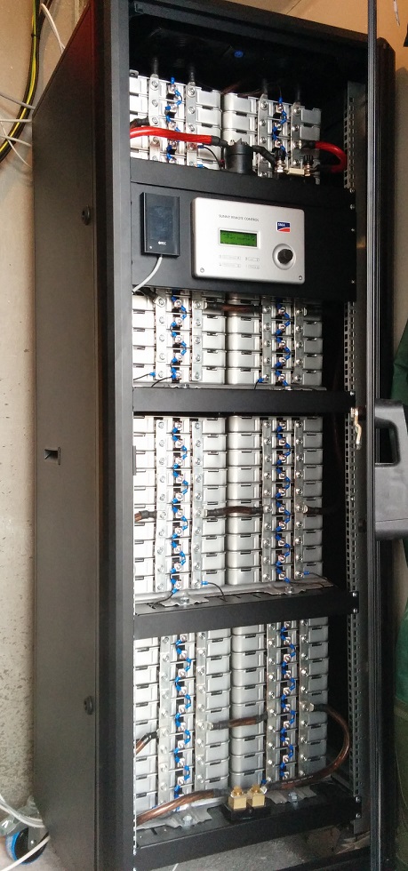
I expanded my "nissan Leaf battery module". Now it contains 70 cells, about 35KWH.
Why not simply break the Tesla battery pack down to the bare cells, then add 3.party BMS systems.. there are plenty of options out there.
Building with Nissan Leaf modules are really easy, almost like Lego�
Oct 12, 2014
JRP3 Take apart 7,104 individual cells? :scared:�
Oct 12, 2014
LittoDevil Hahahahahahahaha...
I guess building with Tesla's modules are easy too but much bigger...
Larry�
Oct 12, 2014
offpist No, not quite what I had in mind.
Is it possible to rearrange all cells in one module so they are all in parallel?
It will of-course involve cutting some connections, and welding on some new ones.
Now its 4,2+4,2+4,2+4,2+4,2+4,2=25,2 V Right?
Put them all in parallel and it would be much easier to build a descent battery module out of it.
If each module was 4,2V,you connect 14 in series, and there you go.. A great 48V package.
Most 48V inverters and chargers can work well withing the range of 40-60V.
Or 7S2P to make 24V battery packs.�
Oct 12, 2014
scaesare Being in series, it also presents the same problem of limiting the entire pack to the potential of the lowest cell. Thus if a single large format cell begins to fail and degrade, the entire pack will be subject to the level of charge the lowest cell can accomodate.�
Oct 12, 2014
wk057 That's basically what I've done.
See my very temporary test setup here: Plan: Off grid solar with a Model S battery pack at the heart - Page 9
The pack is 44.4V nominal in this setup (3.7V per cell) which works fine with the 48V inverters I've chosen. It seems when the voltage gets in the lower 40's the inverter output voltage sags a bit, but it still works.�
Oct 12, 2014
offpist Ah, I see.
But in that way it would be very difficult to make an BMS solution.
The way I suggest, would make that very easy.�
Oct 12, 2014
wk057 The Tesla BMS has a connector going to each set of cells on each module, so, setting up the BMS wouldn't be too hard... just still need 16 setups. I plan to custom make a BMS that utilizes this connector.�
Oct 12, 2014
offpist That`s going to be a LOT of cables.
But yes, I guess it can be done that way.�
Oct 15, 2014
Leigh Obsevations from an Engineer
I've just completed a BMS for a commercial product and thought I would offer some observations.
Balancing.
Shunt balancing is the same method I'm using. Once a pack has been top balanced there is usually very little else to do. Total pack capacity is limited by the lowest capacity of a paralleled cell group.
There are ways to shuttle power around using switched capacitor, and or inductive (dc-dc) methods, but these are costly and add a whole lot of complexity to working out your failure mode analysis.
In fact, once initially balanced, future balancing has nothing to do with different cell capacities, but different internal cell resistances and leakage rates.
Reliability.
There would have been some noisy debates in the engineering team about this one. The tradeoffs of using higher capacity prismatic cells vs low capacity cylindrical cells is a hard problem.
eg. If one cell out of 7000 fails open circuit (or blows the protection fuse with an internal short circuit), the capacity of the entire pack is reduced by the number of seriesed cells. So for 16S system if one 5Wh cell fails, it reduces the pack by 16 x, so 80Wh.
Worst case is if one cell became leaky. This prematurely discharges a group (requiring constant re balancing) but with no hope of isolation the faulty cell.
There was a suggestion of having an ASIC per cell. This could disconnect the faulty cell, but on a 7000 cell pack this would add a lot more failure modes and significant cost that would be worse than the occasional cell failing.
The ASIC idea might have legs for a prismatic high cell capacity system, but not for cylindrical cells.
Effort is better spent on making high quality cells, rather than trying to work around them the complex electronics.
Future
If I had a crystal ball of what the future would be. I think the anode/cathode materials will improve to reduce impedance (so less heat in high charge/discharge), increase cycle & calendar life, and improve combustion safety to a point where where larger prismatic cells will be more viable. Having a prismatic with 100 times the capacity of a cylidrical makes it more economic to manufacture, maintain, and with more opportunity for electronics to intervene.
Wearing my systems engineering hat, the current Tesla solution 'feels right' given the current state of tech.
I think the genius of Musk is having both a good understanding of engineering AND the ability organize capital & labour. It is rare to find both skills in one person.�
Oct 23, 2014
JRP3 Data point regarding cell capacity from the AAB report on Tesla:
http://www.advancedautobat.com/industry-reports/2014-Tesla-report/Extract-from-the-Tesla-battery-report.pdf�
Không có nhận xét nào:
Đăng nhận xét