Feb 5, 2016
garygid We also had no problems with the LEAF when we accidently used the Regular Receive mode (with ACK).
Perhaps our one-time problem with the Model S was with something other than the ACK.
When I am able to Log again, I will first get it working with listen mode, since my AVR-CAN
boards now have the TX solder jumper removed. Then I will try the same hardware and
software in the proper Receive Mode (with the TX solder jumper replaced).
Thanks for sharing your very helpful experience with us.
Cheers, Gary�
Feb 5, 2016
vitaliy You nailed it. Couldn't agree more.�
Feb 5, 2016
Andyw2100 Awesome!�
Feb 5, 2016
hans I thought I was buying a very expensive but extremely cool 17" touchscreen Software Development Kit with some lighted visors ;-)�
Feb 6, 2016
MsElectric The lighted visors are optional...
 �
�
Feb 6, 2016
SUPRKAR We were promised lighted visors..Never got them!!! Promises, promises.�
Feb 6, 2016
dhanson865 Naked Eyes - Promises Promises - YouTube�
Feb 9, 2016
garygid With the Nissan LEAF, we investigated its 4 CAN buses, and found some useful data,
and others discovered how to Request Data (like the 96 cell voltages) and interpret
the results. They made an excellent Leaf Spy Android app, to run on a smartphone
and connect via bluetooth locally to a CAN-to-Bluetooth dongle attached to the LEAF's
Diagnostics connector.
This app was programmed for Android using B2A, and LeafSpy had a free LeafSpy Lite
to test out your dongle and phone (showing a vertical bar graph of the 96 cell voltages)
before buying the $10 LeafSpy app. Then, a LeafSpy Pro was created, offered for $15,
that would read the Diagnostic Trouble Codes, etc. Eventually there was even a twin app
that supports iOS phones.
Sense you have located some useful "hidden" data on the 4 Model S CAN buses, it might
be possible to get a copy of the LeafSpy B2A-based program, and modify it for use with the
Model S (and X). I will be speaking to the program owner soon about this.
Perhaps there us someone here who has the time, talent, and temperment for this
programming project to help out the MS and upcoming MX community?
If you are capable, or want to learn, and seriously interested, please send me
a Private Message with your contact information and I will email or call.�
Feb 9, 2016
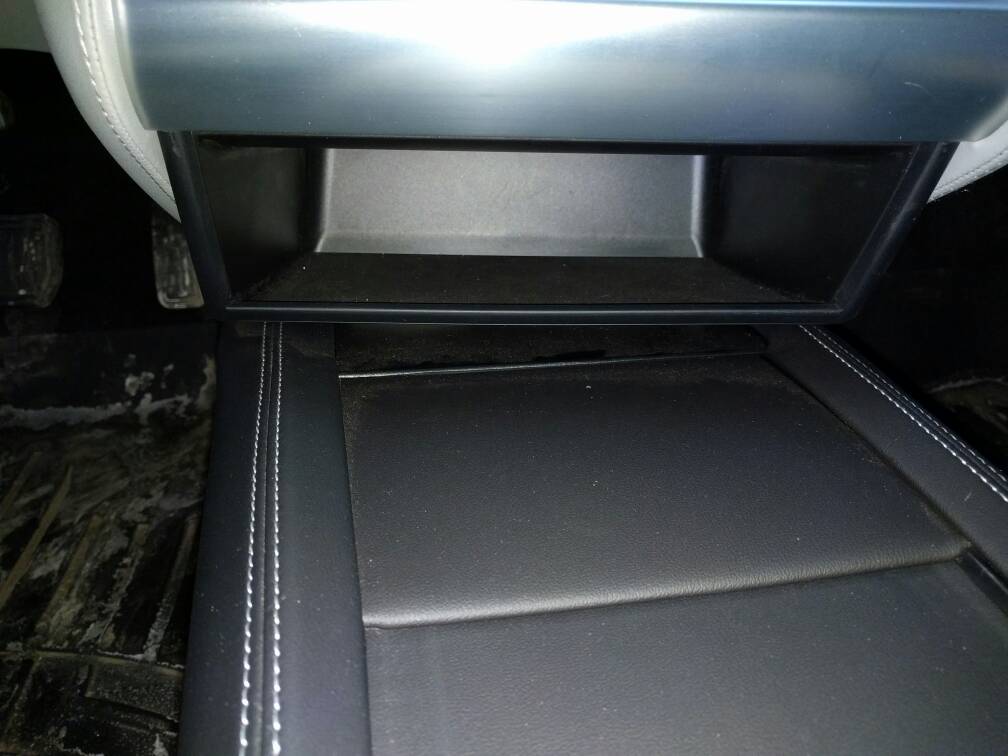
llavalle Quick one for you guys : to access the CAN connector behind the MCU, you have to remove the cubby right? Lets say you have the premium center console installed... Do you need to remove it?
 �
�
Feb 9, 2016
wk057 Dunno about the console. To access the connector I just pull down on the front of the cubby until the front two clips pop out, then I can fetch the connector without actually removing it.�
Feb 9, 2016
llavalle Yeah, ok... Well, it means the center console needs to be removed.. meh.. I can get the cubby to go down about 1/4in to 1/2in but then it's sitting firmly on the console... and I can't even see a gap at the top.
Well, well, well...�
Feb 9, 2016
MikeBur Easter Egg discovery?
Wk, et al. Have you attempted to find any additional Easter eggs with your level of access, eg 007, 42, etc?
Perhaps these are encrypted in the image, though hopefully not... ;-)�
Feb 9, 2016
zdre I finally made a cable and logged data with CANtact. I have a 40kWh so may have some interesting numbers.
Got it working pretty quickly thanks to @Obrien28 's can-utils and @wk057 's decoding. I'm working on enhancing the script to parse more data. You may see a pull request soon") �
�
Feb 9, 2016
smac These are the clips:
I'd say they are slightly over 1/2" (from memory), so it sounds like clearance will be tight.�
Feb 10, 2016
Cyclone What would the service center do if they needed to connect to diagnostics for a repair?�
Feb 10, 2016
wk057 I was actually curious about that myself. Surely they're not going to remove the center console every time.
I suppose they could fetch the car's 16 character security token and just use the diagnostics on the CID that way, but that doesn't work for everything.�
Feb 10, 2016
smac Well in my case hopefully vacuum the carpets first :redface::tongue:�
Feb 10, 2016
NOLA_Mike They may very well have to take the console out (note that I don't know, just speculating). The original Model S had the diagnostics connector behind the left (driver's side) panel of the dash near the door. It's possible when they moved it to behind the cubby in the center console they did it without thinking about cars that had the center console.�
Feb 10, 2016
obrien28 Great to hear, I wrote those scripts out of frustration because I needed something to do serious logging/saving, all Eric had at the time was some 5 line python snippets that showed you the bare minimum to connect to the CANtact and log a frame. Now I just recently added command line arguments to run the program and as part of that added some special flags to enable decoding of the motor and battery data (only the rear DU since I don't have a D) thank you wk057!
That all said I am definitely not a software guy, so any help to improve functionality is much appreciated. If you want to PM me your git email/username then I can add you as a contributor.
Just so everyone is on the same page these are the scripts he is referring to, I'm planning on maybe doing a forum post about logging data using the CANtact, at $60 and fully open HW/SW it makes a nice cheap and cheerful device that even non techno-genius owners can use and not have to take out a loan to pay for.�
Feb 10, 2016
llavalle I'll try it out tonight. Removing the sides of the console is pretty easy : you just pull them on each side. I just hope I don't have to unscrew the console's center part (4 screws) to access the connector.
One thing for sure, I retested this morning and with the console installed, there is now way the cubby can be pulled down enough to get to the connector.�
Feb 10, 2016
zdre My git user name is also zdre. I spend a good amount of time optimizing software performance at work, so am sure I can contribute some improvements.
I using a low-power netbook to log the data, and it seems to be missing many frames. It took me about 5 10,000-frame attempts to actually capture Battery Odometer frame. It seemed that the netbook was not pulling them off CANtact fast enough. I am trying to enhance logging performance to log as much as possible on low-end hardware (maybe even connecting CANtact to a Raspberry Pi) This would require the serial communication to happen on a separate thread from any parsing and file output.
How many frames are you able to capture per second when idle? I am yet to try a capture using a higher-spec laptop.�
Feb 10, 2016
zdre Here are some of my numbers when fully charged:
Nominal Energy Pack Full: 56.6 kWh
Nominal Energy Remaining: 39.2 kWh
Expected Energy Remaining: 40.8 kWh
Ideal Energy Remaining: 39.2 kWh
Energy (Bricking?) Buffer: 1.4 kWh
Pack Voltage: 336.50
Battery Odometer: 34172
SoC UI: 69%
I am not sure what the difference between Expected and Ideal energy remaining.�
Feb 10, 2016
jpet This is interesting... As what voltage are your cells when you are at 100% SoC? I'm curious how Tesla limited the usable capacity of your battery.�
Feb 10, 2016
wk057 336.50 / 84 = 4.00V... which seems a bit high for 69% SoC... was this while still charging?
- - - Updated - - -
The power train bus is easily a few thousand frames per second. It's likely not the laptop but the CAN logger that isn't catching them all.�
Feb 10, 2016
zdre They limited the capacity by only allowing it to charge to ~69%... so I cannot charge any more
I was plugged in and had heat on at that time, so charger was probably applying voltage to the pack. Will look what pack voltage is when just completed charging and not plugged in.
Theoretically, the CANtact adapter is supposed to be internally buffering the frames on the chip, so it should not be losing frames unless you can't pull them fast enough through USB... but I really do not know what is actually going on.�
Feb 10, 2016
obrien28 Just to add something, the ID I'm using for voltage is 102, based on one of my colleagues decodes he thought the pattern was (B3*256) + (B2/100), according to sheet from wk057 B1/0 is the total pack voltage, and B2/3 is pack current, based on wk's research and privileged access I'm more likely to believe his interpretation, I'll update the script accordingly.�
Feb 10, 2016
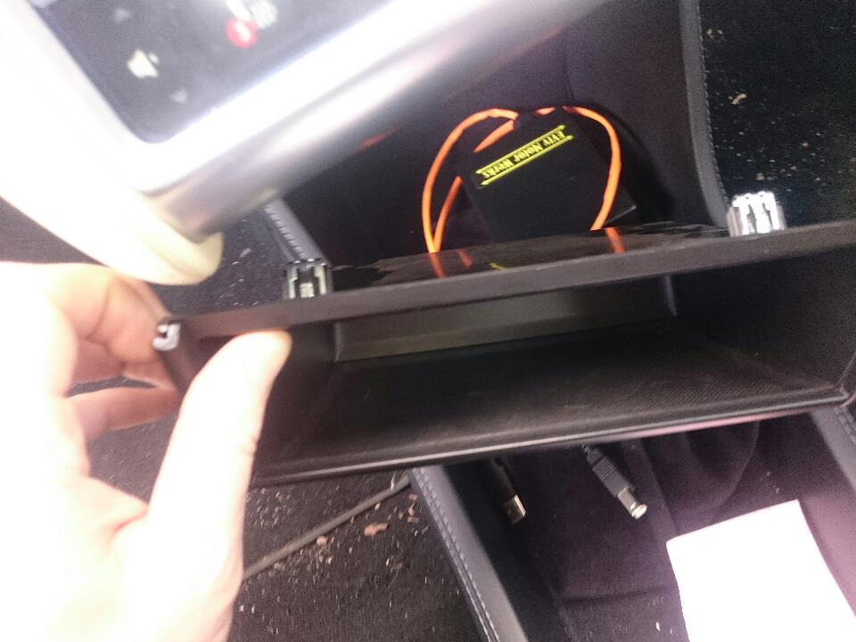
llavalle Mistery solved.
I removed the console (10min job) and there was nothing behind...
Then I saw the 4pin ethernet connector on the right.. Followed the harness and bam, voila:
Simply pull out the right trim from the center bump and you're good to go, the connector's right there!�
Feb 10, 2016
Ingineer Wow, this means your pack will never top balance. Scary!�
Feb 10, 2016
zdre Service Center will do a full charge at the yearly service if requested... But many people never actually charge to 100% even though they can.
- - - Updated - - -
The voltage while not charging showed 326V
EDIT: not sure this is right any more.�
Feb 10, 2016
wk057 Interesting. This is from 0x102? I'd definitely be interested in what the whole array from 0x6F2 shows for your pack... (CAN IDs from memory...)�
Feb 10, 2016
TheBlackKnight The power train bus has about 2200 frames per second as far as I remember. That's somewhere in the neighborhood of 40% bus utilization.
The CANTact firmware doesn't use interrupt driven reception but does seem to use the hardware FIFO. I believe that should be at least 3 deep but I don't know. It also pretty tightly monitors for new frames so it shouldn't be missing any. Though, a three deep buffer means that you can't store four frames or more in between loops in the main firmware.
The USB interface is a bit strange. It is polled which most people probably don't expect. Essentially the host polls the connected devices to see if they want to do something. You can send a decent amount when it is your turn but you have to buffer until then. I think the default poll time is something like 10ms. At the data rate on the power train bus that could be something like 20-22 frames per USB transaction. A CAN frame is probably only like 30-40 bytes even in ascii output so you're looking at maybe 600 or so bytes. If the USB side is using a 512 byte buffer then this would be a problem. But, I think you can set a buffer size of like 4096 bytes or something for USB so presumably that hasn't happened.
That leaves the software side on the PC. Python isn't really known for speed but I would think that it would be able to handle the comparatively slow data rate of CAN. Even the text mode data stream that CANtact uses can't be that much. 2200 frames per second * 30 bytes per frame (just a guess) is a whole 66,000 bytes.
So, not sure why it would drop frames, doesn't seem like it should have trouble.
Of course, I know someone whose products can do 5000 frames per second with no drops at all. B)�
Feb 10, 2016
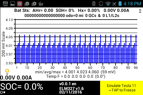
Turbo3 Work on TMS-Spy has started and the basic code to move the 0x6F2 Frame data and scale it into the cell voltage array is done. Plotting is the same as LeafSpy since Leaf also has 96 cells so once the array is loaded with Tesla data it will be displayed using the same code. Temperature display code will need to be changed to go from the 3 or 4 sensors the Leaf has to 32 on the Tesla but that is not a big deal. To keep things the same the cell voltage is stored as an integer millivolt value so resolution is kept to 0.001 volts.
Until I get a cable and access to a Tesla I will use emulation mode in the app which allows a set of stored frames to be feed into the code as if it came from the serial port.�
Feb 11, 2016
smac Quick Q. for the SavvyCAN experts...
How is the time stamp defined?�
Feb 11, 2016
TheBlackKnight The time stamp you see normally is microseconds since the capture hardware started. That gives you a *very* precise timestamp but it is somewhat cumbersome to work with. It tends to be easier to read if you go to File->Preferences->Display time in seconds. Then the next time you start the program (and thereafter) it'll display the timestamps in seconds which tends to be easier to read.�
Feb 11, 2016
smac Thanks for the confirmation. I had assumed it was in microseconds, but wanted to double check (in case it was an internal counter or similar, and the timings were coincidental.)
Microseconds works perfectly for my purposes (grabbing a straight text log from a run, then feeding it into some graphing stuff, where I can scale appropriately to 100's of a second), but handy to know.�
Feb 11, 2016
Ingineer Nice to see you over here Jim! I'll be happy to give you access to my little fleet if you wanna come by. =)�
Feb 11, 2016
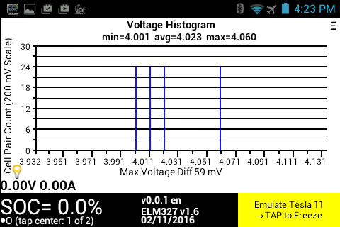
Turbo3 Here are some screenshots using emulated frames that are in the Tesla format. I just repeated the same four voltages for each of the 24 frames to make frame generation easier.
 �
�
Feb 11, 2016
apacheguy Can someone explain why there is so much traffic? I mean why do we need to know motor rpm 100 times a second? Seems crazy. 10 Hz should be the maximum frequency sent out. Interpolation is arguably just as robust if finer scale is needed, but frankly I don't see the need. Most cars have bus rates that are much, much less than the Model S from what I gather.�
Feb 11, 2016
wk057 Most cars don't have electric motors that can be manipulated "on the millisecond level", to use an Elon Musk term.�
Feb 11, 2016
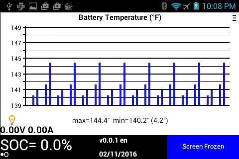
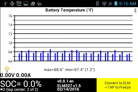
Turbo3 Here is the battery temperature graph. As I understand it there are thought to be pairs of sensors one on the inlet the other on the outlet coolant port. For that reason I have grouped the temperatures in pairs. The data is from sample CAN frames in the Tesla format. I would assume different pack sizes have a different number of sensors. How is this reflected on the CAN bus? Same number of frames but some have zero for data or less frames?
 �
�
Feb 12, 2016
chickensevil To echo wk057, things like TC and ESP are so amazing on this car simply *because* of the response times on their devices. You want to change the RPM of the motor in order to adjust for loss of traction. If you were only getting data every 10th of a second then you could only make adjustments at that rate. And since you would get a piece of data, and then issue an adjustment, and then have to wait for the data to come back saying it had changed, if you were dealing at each thing happening every say, 10th of a second, then you are talking 3/10ths of a second to receive, send, and receive back again. This is a terribly high response time if you are trying to make adjustments on the fly to keep the car from losing control. Instead all of that can happen in 3ms, which is why you can feel the car making adjustments while driving in slippery conditions, but it doesn't even have time to light up the TC/ESP alarms on the instrument cluster because the changes are happening too fast.
Note that TC/ESP is just one area where faster message rates would be helpful.�
Feb 12, 2016
scaesare And for context, at 60MPH, that 3/10ths of a second is 26.4 feet.... more than an entire car length's worth of travel before the very first feedback of any attempt at controlling things.
For high-speed corrections, the bus is capable of the speeds, so why not take advantage of it?�
Feb 12, 2016
Cyclone This (plus the next point) is exactly how I explain why my RWD S is better on the snow/ice than my 4WD 4Runner (and yes, I know 4WD does nothing for stopping). The intricate control the S has, coupled with the fact that the computer could override my throttle inputs puts its TC/VSC far ahead. The 4Runner can redirect power to each of the 4 wheels, it can deploy braking, but it cannot control the idiot pressing the pedal to the floor. The S can.�
Feb 12, 2016
wk057 So, coming back to this thread's original topic....
I've been working off and on with an idea for instrument cluster augmentation. So, I've started with native code that runs on the IC that picks out the variables I want from the ethernet frame broadcasts (which are basically CAN encapsulated in UDP). Pretty sure I have everything I could need from there, except I haven't exactly worked out the steering controls.... mainly because I don't have a steering wheel on my bench. lol. But my goal is to basically take over the display on the IC. There's tons of data available, so should be fun.
I suck at UIs, though, so my IC will probably look more like a linux command line when I'm done vs something a UI/graphic designer came up with. But, I intend to have tons of data displaying. An example is going to be basically a built in VBOX type of thing where it'll graph 0-60 runs and such. Should be awesome when I'm done. I'm also going to make it so I can pull up stuff on the CID via the browser to go through data.
A few people have suggested there would be a market for this kind of mod, but I don't think that I'm going to go there with it. I also don't know of a reasonable way to make this possible for others without just giving Tesla a simple way to make it impossible/difficult by patching to make it harder to get root. Someone suggested selling a modded instrument cluster with a steep core charge, since to do this you have to remove the IC anyway.
I have a few projects I need to finish before I get back to this one, but should be fun times ahead.�
Feb 12, 2016
TheBlackKnight Just a quick correction: the fastest frames are sent every 10ms not every 1ms. Still, that is 100 times per second. Receiving a frame that indicates a problem then sending a reply can be done in about 11ms - that is probably the lower bound for response time. If my math is correct that would seem to indicate that the amount of distance the car can cover in that time span (at 60MPH) is about a foot. Also, the inter-frame timing is not set in stone. If a module in the car believes the dung is about to hit the fan it is free to send an emergency message *NOW*. That's partly the reason for the priority scheme in can traffic - lower IDs take precedence over higher IDs. So, things like traction control, steering, and airbags have low IDs and thus can barge onto the bus any time they feel like and override anything else that was being sent. But, normal CAN traffic that relates to traction and such will probably keep its time slot except in emergencies. Still, they can cheat by having replies get triggered by reception such that it isn't really 10ms and you get a frame, 10ms later you send one, 10ms later they send a reply. Instead it is more likely that every 10ms one device sends an important message, another device receives it and instantly replies, then 10ms later the cycle repeats. You'll see that a lot in traffic where things go in bursts. So, likely the time delay is 20ms not 30ms. And, not a lot happens in 20ms.�
Feb 12, 2016
Denarius I wouldn't want a fancy UI. Give me raw data! Tesla should really give us an easy way to do this, otherwise they are going to end up with a bunch of Frankenstein cars driving around so people can get the data they want.�
Feb 12, 2016
MikeBur I'm sure everyone has their GUI of choice, and after playing whack-a-mole with a bunch of my colleagues we aligned on one choice for game data visualization in demo/sample code, imGUI: GitHub - ocornut/imgui: Bloat-free Immediate Mode Graphical User interface for C++ with minimal dependencies�
Feb 13, 2016
garygid Apparently the Cell Voltage info is only on the CAN3 (500k) bus, right?
And, the only "exposed" CAN bus is on the OBD, and it is CAN2 (125k) pins 1 and 9, right?
So, to use Jim's Spy program, which gets data from an OBD dongle, usually bluetooth,
one needs an TDC to OBD adapter. I have a mating connector (and pins) for the TDC,
but not yet an OBD connector like one would find in the car.
However, assuming that I get the connectors and pins, and make a "short" adapter cable
with CAN3 wired to the OBD pins 6 and 14, and connect ground and the "12v", the difficult
part for me is to find a way to get the end of this adapter from behind the cubby out to
the left side of the passenger's footspace. Anybody investigated this aspect?
Thanks, Gary�
Feb 14, 2016
smac My 60 kWh pack behaves subtly differently, and I receive 0x6f2's for 0-20 and 24-30, so I couldn't cut and paste code that relied on the stream being contiguous or having 32 items.
I'm also working in C#, so maybe not the perfect tool for this sort of stuff.
Volts seem a little high seeing as I'm at 79% SOC (could be a 60 thing?). It's 2c ambient here, however the car was on charge overnight and not that long finished.
I would really appreciate if anyone would eyeball my parsing. (I'm basically assuming the 7 bytes sent by the logger are a reverse order bit stream, split in 4 x 14 byte segments.) This seems to give the expected results, with the cells appearing balanced, but I could be missing something.
Msg 01 : 6B 74 1B FD 46 BF D1 11010110001011 10110110001011 11110110001011 11110110001011 4.093v 4.093v 4.094v 4.094v
Msg 02 : 6F 34 1B DD 46 B3 D1 11110110001011 00110110001011 10110110001011 00110110001011 4.094v 4.093v 4.093v 4.093v
Msg 03 : 6C 34 1B CD 46 AF D1 00110110001011 00110110001011 00110110001011 11010110001011 4.093v 4.093v 4.093v 4.093v
Msg 04 : 6B 74 1B FD 46 B3 D1 11010110001011 10110110001011 11110110001011 00110110001011 4.093v 4.093v 4.094v 4.093v
Msg 05 : 6F 34 1B BD 46 B3 D1 11110110001011 00110110001011 11010110001011 00110110001011 4.094v 4.093v 4.093v 4.093v
Msg 06 : 6D 34 1B CD 46 AF D1 10110110001011 00110110001011 00110110001011 11010110001011 4.093v 4.093v 4.093v 4.093v
Msg 07 : 6B 74 1B DD 46 B3 D1 11010110001011 10110110001011 10110110001011 00110110001011 4.093v 4.093v 4.093v 4.093v
Msg 08 : 6B F4 1A BD 46 B7 D1 11010110001011 11010110001011 11010110001011 10110110001011 4.093v 4.093v 4.093v 4.093v
Msg 09 : 6B B4 1A AD 46 AF D1 11010110001011 01010110001011 01010110001011 11010110001011 4.093v 4.092v 4.092v 4.093v
Msg 10 : 6B 34 1B 0D 47 BF D1 11010110001011 00110110001011 00001110001011 11110110001011 4.093v 4.093v 4.094v 4.094v
Msg 11 : 6E 34 1B BD 46 B7 D1 01110110001011 00110110001011 11010110001011 10110110001011 4.094v 4.093v 4.093v 4.093v
Msg 12 : 6D 34 1B ED 46 AF D1 10110110001011 00110110001011 01110110001011 11010110001011 4.093v 4.093v 4.094v 4.093v
Msg 13 : 6B 34 1B FD 46 C3 D1 11010110001011 00110110001011 11110110001011 00001110001011 4.093v 4.093v 4.094v 4.094v
Msg 14 : 6E 34 1B DD 46 BF D1 01110110001011 00110110001011 10110110001011 11110110001011 4.094v 4.093v 4.093v 4.094v
Msg 15 : 6D 34 1B BD 46 B3 D1 10110110001011 00110110001011 11010110001011 00110110001011 4.093v 4.093v 4.093v 4.093v
Msg 16 : 69 34 1B FD 46 BF D1 10010110001011 00110110001011 11110110001011 11110110001011 4.092v 4.093v 4.094v 4.094v
Msg 17 : 6B F4 1A AD 46 B7 D1 11010110001011 11010110001011 01010110001011 10110110001011 4.093v 4.093v 4.092v 4.093v
Msg 18 : 6C F4 1B CD 46 B3 D1 00110110001011 11110110001011 00110110001011 00110110001011 4.093v 4.094v 4.093v 4.093v
Msg 19 : 6B 34 1B DD 46 BB D1 11010110001011 00110110001011 10110110001011 01110110001011 4.093v 4.093v 4.093v 4.094v
Msg 20 : 6B B4 1A AD 46 B3 D1 11010110001011 01010110001011 01010110001011 00110110001011 4.093v 4.092v 4.092v 4.093v
Msg 24 : 20 82 90 B0 20 4C 09 00000100010000 01000010010000 11010000010000 11001010010000 6.64c 7.05c 6.38c 7.26c
Msg 25 : 07 82 8D 20 20 E4 08 11100000010000 01101100010000 01000000010000 10011100010000 6.33c 6.91c 6.27c 6.94c
Msg 26 : 00 02 8C 30 20 F0 08 00000000010000 00001100010000 11000000010000 00111100010000 6.25c 6.83c 6.28c 6.98c
Msg 27 : E8 01 87 B0 1F 58 08 00010111100000 00111000010000 11011111100000 01101000010000 5.95c 6.59c 6.19c 6.51c
Msg 28 : 14 82 89 60 20 B0 08 00101000010000 01100100010000 01100000010000 00110100010000 6.49c 6.71c 6.32c 6.78c
Msg 29 : 02 82 88 A0 20 A8 08 01000000010000 01000100010000 01010000010000 01010100010000 6.27c 6.66c 6.37c 6.76c
Msg 30 : 1F 82 8F 70 20 EC 08 11111000010000 01111100010000 11100000010000 11011100010000 6.62c 7.00c 6.33c 6.97c�
Feb 14, 2016
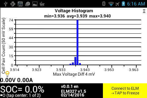
Turbo3 smac, Thanks for posting that data it allowed me to understand the mapping and update TM-Spy so it now correctly displays voltage and temp data taken from a real Tesla.
I am impressed with how well the battery pack is balanced. Temps also show the difference between inlet and outlet temps.
 �
�
Feb 14, 2016
wk057 Hmm... not sure how your logger works, but I don't think there is anything reversed. I ran this through my parser and got the same results you did, though. However, are the values you are pasting here altered? This is what I reconstructed from your info above using the hex values (I may have the indexes wrong):
Outputs:Code:000006F2 00 6B 74 1B FD 46 BF D1 000006F2 01 6F 34 1B DD 46 B3 D1 000006F2 02 6C 34 1B CD 46 AF D1 000006F2 03 6B 74 1B FD 46 B3 D1 000006F2 04 6F 34 1B BD 46 B3 D1 000006F2 05 6D 34 1B CD 46 AF D1 000006F2 06 6B 74 1B DD 46 B3 D1 000006F2 07 6B F4 1A BD 46 B7 D1 000006F2 08 6B B4 1A AD 46 AF D1 000006F2 09 6B 34 1B 0D 47 BF D1 000006F2 0A 6E 34 1B BD 46 B7 D1 000006F2 0B 6D 34 1B ED 46 AF D1 000006F2 0C 6B 34 1B FD 46 C3 D1 000006F2 0D 6E 34 1B DD 46 BF D1 000006F2 0E 6D 34 1B BD 46 B3 D1 000006F2 0F 69 34 1B FD 46 BF D1 000006F2 10 6B F4 1A AD 46 B7 D1 000006F2 11 6C F4 1B CD 46 B3 D1 000006F2 12 6B 34 1B DD 46 BB D1 000006F2 13 6B B4 1A AD 46 B3 D1 000006F2 18 20 82 90 B0 20 4C 09 000006F2 19 07 82 8D 20 20 E4 08 000006F2 1A 00 02 8C 30 20 F0 08 000006F2 1B E8 01 87 B0 1F 58 08 000006F2 1C 14 82 89 60 20 B0 08 000006F2 1D 02 82 88 A0 20 A8 08 000006F2 1E 1F 82 8F 70 20 EC 08
So, basically the same as you, assuming your hex values above are exactly from the logger and not reversed in some way. 4.09V seems very high for 79% SoC unless the car was charging or otherwise had the charger enabled (running the heat from shore power or something). Mind sharing the raw log for 6F2 (one of all indexes) and 102 (a couple would be fine)?Code:BMS_brick01_V_UI: 4.092795 V BMS_brick02_V_UI: 4.093405 V BMS_brick03_V_UI: 4.094015 V BMS_brick04_V_UI: 4.094015 V BMS_brick05_V_UI: 4.094015 V BMS_brick06_V_UI: 4.0931 V BMS_brick07_V_UI: 4.093405 V BMS_brick08_V_UI: 4.0931 V BMS_brick09_V_UI: 4.0931 V BMS_brick10_V_UI: 4.0931 V BMS_brick11_V_UI: 4.0931 V BMS_brick12_V_UI: 4.092795 V BMS_brick13_V_UI: 4.092795 V BMS_brick14_V_UI: 4.093405 V BMS_brick15_V_UI: 4.094015 V BMS_brick16_V_UI: 4.0931 V BMS_brick17_V_UI: 4.094015 V BMS_brick18_V_UI: 4.0931 V BMS_brick19_V_UI: 4.092795 V BMS_brick20_V_UI: 4.0931 V BMS_brick21_V_UI: 4.093405 V BMS_brick22_V_UI: 4.0931 V BMS_brick23_V_UI: 4.0931 V BMS_brick24_V_UI: 4.092795 V BMS_brick25_V_UI: 4.092795 V BMS_brick26_V_UI: 4.093405 V BMS_brick27_V_UI: 4.093405 V BMS_brick28_V_UI: 4.0931 V BMS_brick29_V_UI: 4.092795 V BMS_brick30_V_UI: 4.092795 V BMS_brick31_V_UI: 4.092795 V BMS_brick32_V_UI: 4.093405 V BMS_brick33_V_UI: 4.092795 V BMS_brick34_V_UI: 4.09249 V BMS_brick35_V_UI: 4.09249 V BMS_brick36_V_UI: 4.092795 V BMS_brick37_V_UI: 4.092795 V BMS_brick38_V_UI: 4.0931 V BMS_brick39_V_UI: 4.09432 V BMS_brick40_V_UI: 4.094015 V BMS_brick41_V_UI: 4.09371 V BMS_brick42_V_UI: 4.0931 V BMS_brick43_V_UI: 4.092795 V BMS_brick44_V_UI: 4.093405 V BMS_brick45_V_UI: 4.093405 V BMS_brick46_V_UI: 4.0931 V BMS_brick47_V_UI: 4.09371 V BMS_brick48_V_UI: 4.092795 V BMS_brick49_V_UI: 4.092795 V BMS_brick50_V_UI: 4.0931 V BMS_brick51_V_UI: 4.094015 V BMS_brick52_V_UI: 4.09432 V BMS_brick53_V_UI: 4.09371 V BMS_brick54_V_UI: 4.0931 V BMS_brick55_V_UI: 4.093405 V BMS_brick56_V_UI: 4.094015 V BMS_brick57_V_UI: 4.093405 V BMS_brick58_V_UI: 4.0931 V BMS_brick59_V_UI: 4.092795 V BMS_brick60_V_UI: 4.0931 V BMS_brick61_V_UI: 4.092185 V BMS_brick62_V_UI: 4.0931 V BMS_brick63_V_UI: 4.094015 V BMS_brick64_V_UI: 4.094015 V BMS_brick65_V_UI: 4.092795 V BMS_brick66_V_UI: 4.092795 V BMS_brick67_V_UI: 4.09249 V BMS_brick68_V_UI: 4.093405 V BMS_brick69_V_UI: 4.0931 V BMS_brick70_V_UI: 4.094015 V BMS_brick71_V_UI: 4.0931 V BMS_brick72_V_UI: 4.0931 V BMS_brick73_V_UI: 4.092795 V BMS_brick74_V_UI: 4.0931 V BMS_brick75_V_UI: 4.093405 V BMS_brick76_V_UI: 4.09371 V BMS_brick77_V_UI: 4.092795 V BMS_brick78_V_UI: 4.09249 V BMS_brick79_V_UI: 4.09249 V BMS_brick80_V_UI: 4.0931 V BMS_BMBtemp01_UI: 6.6368 C BMS_BMBtemp02_UI: 7.0516 C BMS_BMBtemp03_UI: 6.3806 C BMS_BMBtemp04_UI: 7.259 C BMS_BMBtemp05_UI: 6.3318 C BMS_BMBtemp06_UI: 6.9052 C BMS_BMBtemp07_UI: 6.2708 C BMS_BMBtemp08_UI: 6.9418 C BMS_BMBtemp09_UI: 6.2464 C BMS_BMBtemp10_UI: 6.832 C BMS_BMBtemp11_UI: 6.283 C BMS_BMBtemp12_UI: 6.9784 C BMS_BMBtemp13_UI: 5.9536 C BMS_BMBtemp14_UI: 6.588 C BMS_BMBtemp15_UI: 6.1854 C BMS_BMBtemp16_UI: 6.5148 C BMS_BMBtemp17_UI: 6.4904 C BMS_BMBtemp18_UI: 6.71 C BMS_BMBtemp19_UI: 6.3196 C BMS_BMBtemp20_UI: 6.7832 C BMS_BMBtemp21_UI: 6.2708 C BMS_BMBtemp22_UI: 6.6612 C BMS_BMBtemp23_UI: 6.3684 C BMS_BMBtemp24_UI: 6.7588 C BMS_BMBtemp25_UI: 6.6246 C BMS_BMBtemp26_UI: 7.0028 C BMS_BMBtemp27_UI: 6.3318 C BMS_BMBtemp28_UI: 6.9662 C�
Feb 14, 2016
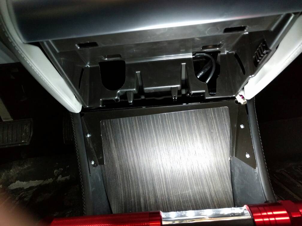
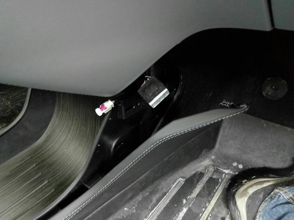
Ingineer Easy, just pull off the 2 panels on the side of the console and the footwell area, then it will be an easy matter to route the cables.�
Feb 14, 2016
obrien28 I was just going to suggest the same thing, llavale did something similar because he had a center console in the way (I later found out why after reading a service bulletin), here is a photo if it helps Gary.
 �
�
Feb 14, 2016
smac Sure no problem (GVRET raw output, though probably not the same exact frames)
137229312,000006F2,false,Rx,0,8,00,6F,F4,1B,ED,46,B3,D1,
137329317,000006F2,false,Rx,0,8,01,6A,74,1B,FD,46,BB,D1,
137429311,000006F2,false,Rx,0,8,02,6E,34,1B,ED,46,B7,D1,
137529311,000006F2,false,Rx,0,8,03,6C,B4,1B,ED,46,AF,D1,
....
and a 102:
137531470,00000102,false,Rx,0,8,41,86,05,A7,09,4E,EC,00,
Finally the C# code (sorry being lazy with LINQ and iteration)
public override void Init(byte[] data)
{
// Get 7 bytes of real data, and turn them into bits
var ba = new BitArray(data.Skip(1).Take(7).ToArray());
var vs = new double[4];
// we are looking for 4 values
for (int j = 0; j < 4; j++)
{
int v1 = 0;
// loop thru 14 bits and add each bit value in its correct place.
for (int i = 0; i < 14; i++)
{
if (ba[(j * 14) + i])
{
v1 += (1 << i);
}
}
// perform scaling. Voltages in message parts < 24, otherwise temperature.
if (data[0] < 24)
vs[j] = v1 * 0.000305;
else
vs[j] = v1 * 0.0122;
}
- - - Updated - - -
And at 89% SOC
Msg 00 : 8B F5 61 5D 58 1B D6 11010001101011 11100001101011 10100001101011 01100001101011 4.181v 4.179v 4.179v 4.179v
Msg 01 : 85 35 61 7D 58 23 D6 10100001101011 00100001101011 11100001101011 00010001101011 4.179v 4.179v 4.179v 4.180v
Msg 02 : 88 F5 61 6D 58 17 D6 00010001101011 11100001101011 01100001101011 10100001101011 4.180v 4.179v 4.179v 4.179v
Msg 03 : 86 B5 61 6D 58 13 D6 01100001101011 01100001101011 01100001101011 00100001101011 4.179v 4.179v 4.179v 4.179v
Msg 04 : 83 B5 61 9D 58 1B D6 11000001101011 01100001101011 10010001101011 01100001101011 4.178v 4.179v 4.180v 4.179v
Msg 05 : 8B 35 61 3D 58 17 D6 11010001101011 00100001101011 11000001101011 10100001101011 4.181v 4.179v 4.178v 4.179v
Msg 06 : 84 35 61 5D 58 13 D6 00100001101011 00100001101011 10100001101011 00100001101011 4.179v 4.179v 4.179v 4.179v
Msg 07 : 83 75 61 6D 58 1B D6 11000001101011 10100001101011 01100001101011 01100001101011 4.178v 4.179v 4.179v 4.179v
Msg 08 : 86 F5 60 5D 58 17 D6 01100001101011 11000001101011 10100001101011 10100001101011 4.179v 4.178v 4.179v 4.179v
Msg 09 : 83 F5 60 3D 58 0F D6 11000001101011 11000001101011 11000001101011 11000001101011 4.178v 4.178v 4.178v 4.178v
Msg 10 : 83 35 61 9D 58 23 D6 11000001101011 00100001101011 10010001101011 00010001101011 4.178v 4.179v 4.180v 4.180v
Msg 11 : 88 B5 61 7D 58 27 D6 00010001101011 01100001101011 11100001101011 10010001101011 4.180v 4.179v 4.179v 4.180v
Msg 12 : 86 F5 61 7D 58 1B D6 01100001101011 11100001101011 11100001101011 01100001101011 4.179v 4.179v 4.179v 4.179v
Msg 13 : 85 75 61 7D 58 23 D6 10100001101011 10100001101011 11100001101011 00010001101011 4.179v 4.179v 4.179v 4.180v
Msg 14 : 87 B5 61 5D 58 33 D6 11100001101011 01100001101011 10100001101011 00110001101011 4.179v 4.179v 4.179v 4.181v
Msg 15 : 86 F5 61 7D 58 1F D6 01100001101011 11100001101011 11100001101011 11100001101011 4.179v 4.179v 4.179v 4.179v
Msg 16 : 85 B5 61 CD 58 2F D6 10100001101011 01100001101011 00110001101011 11010001101011 4.179v 4.179v 4.181v 4.181v
Msg 17 : 86 35 61 5D 58 13 D6 01100001101011 00100001101011 10100001101011 00100001101011 4.179v 4.179v 4.179v 4.179v
Msg 18 : 83 35 61 7D 58 0F D6 11000001101011 00100001101011 11100001101011 11000001101011 4.178v 4.179v 4.179v 4.178v
Msg 19 : 83 75 61 3D 58 13 D6 11000001101011 10100001101011 11000001101011 00100001101011 4.178v 4.179v 4.178v 4.179v
Msg 20 : 85 F5 60 3D 58 17 D6 10100001101011 11000001101011 11000001101011 10100001101011 4.179v 4.178v 4.178v 4.179v
Msg 24 : 58 03 DA 80 34 04 0E 00011010110000 00010110110000 00010010110000 10000001110000 10.44c 10.64c 10.25c 10.94c
Msg 25 : 47 C3 DA 40 34 D4 0D 11100010110000 11010110110000 00100010110000 10101110110000 10.24c 10.68c 10.20c 10.80c
Msg 26 : 32 C3 D4 90 32 94 0D 01001100110000 11001010110000 10010100110000 10100110110000 9.98c 10.38c 9.87c 10.60c
Msg 27 : DE 82 C9 80 31 60 0C 01111011010000 01100100110000 00011000110000 00011000110000 8.95c 9.83c 9.66c 9.66c
Msg 28 : 48 83 D1 80 34 78 0D 00010010110000 01100010110000 00010010110000 01111010110000 10.25c 10.22c 10.25c 10.52c
Msg 29 : 46 03 D7 D0 34 94 0D 01100010110000 00111010110000 10110010110000 10100110110000 10.22c 10.49c 10.31c 10.60c
Msg 30 : 5E 43 DC E0 33 88 0D 01111010110000 10001110110000 01111100110000 01000110110000 10.52c 10.75c 10.13c 10.57c
Example GVRET item:
109195540,000006F2,false,Rx,0,8,00,8B,F5,61,5D,58,1B,D6,
And next 102:
109187754,00000102,false,Rx,0,8,FF,88,05,A7,08,4E,F9,00,�
Feb 14, 2016
smac OT, but I had to double take there!
 �
�
Feb 14, 2016
kennybobby The code looks good to me, just striping off 14 bits at a time in the order received, and then packing them together to form the value.
What looks confusing to me is that the printing routine is displaying the binary value in reversed bit order, i.e. the lsb is at the left and msb to the right.
For example take the first binary listed above, 11010001101011b, = 13419d = 4.095 Volts, but you are showing cell 1 to be 4.181 V.
If i reverse the displayed bit order, 11010110001011b, = 13707d = 4.1806 V, which is your cell 1 voltage value.
And another way to check, looking at the hex bytes value for cell one should be 0x358B = 13707d.
Your voltages may be higher for a given SOC since you have the high capacity 60 pack...lol�
Feb 14, 2016
apacheguy @wk, @Ingineer - What's going on here? From earlier in this thread, the passive cooling target was 30 C. Now it's at 52 C?! This is on 7.1.�
Feb 15, 2016
cynix See this post by wk: Let the hacking begin... (Model S parts on the bench) - Page 43
wk said Max Battery Power increases cooling targets to 50/52�C, not sure why this screenshot shows 52/55�C.�
Feb 15, 2016
smac Aha! It's the C# BitArray class. (Something I admit I never use in my day job)
{0x01, 0x02, 0x04} => {1,0,0,0,0,0,0,0, 0,1,0,0,0,0,0,0, 0,0,1,0,0,0,0} (so yes lsb is leftmost, and I'm just iterating this to produce a string for the binary output)
Well that is certainly an interesting point, do the 60's use more of the voltage range, or have I misinterpreted the data (I worry more about the latter as this stuff is quite a way from my area of expertise.)�
Feb 15, 2016
garygid Ok, this MS has the center console installed, but the cubby/shelf is gone, right?
What if there is no console ... then remove the cubby, bend the TDC cable to the
right, and put the TD Connector through some large hole?
And, how does one get the two rear clips of the cubby back in place, please?
I will try again today, but suggestions for the no-console case welcomed.
Thanks�
Feb 15, 2016
kennybobby Do you have any 100% charged data yet? It looks like from your data we have seen
79% ~ 4.09 V
89% ~ 4.179 V
lots of M85 data but not so much M60, lola's sc data put 93% at the charging CV knee with about 24 cells >= 4.19 V. Your cells look evenly balanced.�
Feb 15, 2016
llavalle This is my car. I had just removed the console and cubby - I was looking for the connector. I did reinstall both a couple of minutes later.
As for the rear clips : it takes patience�
Feb 15, 2016
apacheguy This screen is from an S85. It does not have Max Power mode. Even more odd...�
Feb 15, 2016
llavalle Still OT but what exactly did you see before figuring out it was my boot?�
Feb 15, 2016
smac Nope not yet, I generally do < 9 miles each way on my commute, so I'd end up leaving the car at a fairly high SOC. As soon as I get the opportunity, I'm more than happy to do it to fill out the "community dataset".
Seems we have lots of 85 packs investigated (and most effort gone in to tools for those). I hope by adding some data from a rarer pack it helps the broader understanding.
- - - Updated - - -
I didn't. It was just funny as I was rocking a very similar footwear / jeans combo when I saw the thread�
Feb 15, 2016
Ingineer If you made the mistake of not following the instructions and did more than just unsnap the front of the cubby, you are now going to have to take the yacht floor (or carpet if an older S) out of the bowling alley, and on some cars this is a PITA.
Reach your fingers up behind the rear top of the yacht floor and pull towards the rear of the car and try to work the yacht floor piece out. There is a little black piece of plastic that snaps in on either side at rear of the cubby space that must come out in order to re-install the cubby. This piece pulls out straight towards the rear of the car to remove it. So this also means the yacht floor must come out first. Be extremely careful with the front of the yacht floor where it meets the console. If you have the version with rubber all around then you are much less likely to damage something. If not, and the yacht floor has no rubber surround, then be careful not to damage the corners and/or the rear of the console (where the USB ports are, etc). If you have an older S with only carpet, then it's super easy.
I made a couple of hook tools out of thin tempered strips of sheet metal I found in my junk stash that makes this procedure much easier, but again, just go slow and be careful.
Warning to those that have not fully removed the cubby, DO NOT! Just unsnap the front only and let it swing down. If you remove it, you have a lot of tricky expletive-laden work to do in order to get it back together!�
Feb 15, 2016
smac Has there been a design change? My cubby has two plastic tangs at the back, and two corresponding slots in the back of the central storage area. Underneath the slots is a lip which supports the cubby and acts as a guide. It's super simple to install / remove my cubby, but I have neither yacht flooring or premium console. I didn't need to take out any carpet though.
I'll admit to not trying the side panel, and will give that a try. This seems the most universal solution!�
Feb 15, 2016
garygid The "little black piece of plastic that snaps in on either side at rear of the cubby space
that must come out in order to re-install..." ...
is this a piece that extends from the left side to the right side?
After the top of the rug is pulled toward the rear of the car, and the "black piece" is removed by pulling it
toward the rear of the car, the cubby would go into position and up, then the black piece back in, and
finally the top of the rug back in place?
If so, I will try to get the black piece out. Rather sorry that I did not understand (or remember)
the instruction details. When it is all back together, I still do not see where the connector could
come out the right side to get accessed in the passenger footspace.
However, since I am trying to make the TDC accessible, there is some good in my blunder.
with the back of the cubby down about 3/4 inch too far (but the front of the cubby snapped
in place), the cubby is usable, looks reasonable, and there is a narrow v-shaped space for
the cable to/from the TDC (or the TDC to OBD adapter) to enter/exit the space behind the
cubby. Also, there might be enough additional room above the "saggy-down" cubby to
hide both the adapter and the ELM-type dongle.
As a minimum for the TM-Spy, the CAN3 (H and L) would go to the OBD pins 6 (H) and 14 (L),
Ground will connect to OBD pins 5 and 4, and "12v" will connect the "always On power" to OBD pin 16.
Hopefully, I will have the necessary parts "soon", perhaps within a week.�
Feb 15, 2016
pupik Excuse me, how you acquired 59.8kWh?
I tried insert your data from CAN into my SW and I think you have a mistake for all further calculations on the forum for S60 :wink:
so, 59.8kWh is probably typing error?�
Feb 15, 2016
zdre It did turn out to be my crappy netbook not keeping up... python was maxing out one of the threads, so it was able to capture only 300fps. My real laptop was able to capture 1400+fps. It did not look like it was missing any.
Here are my 0x6F2 logs. I have not had time to work on my parser unfortunately.
6f2,0,177,241,108,12,27,207,198
6f2,1,177,241,108,220,26,187,198
6f2,2,175,241,107,236,26,199,198
6f2,3,178,49,109,76,27,211,198
6f2,4,180,49,109,44,27,207,198
6f2,5,178,113,109,60,27,219,198
6f2,6,159,49,104,188,25,127,198
6f2,7,158,241,103,28,27,191,198
6f2,8,174,241,107,252,26,203,198
6f2,9,177,113,109,44,27,211,198
6f2,10,177,241,109,12,27,211,198
6f2,11,178,49,109,76,27,227,198
6f2,12,184,49,110,124,27,227,198
6f2,13,184,49,110,108,27,235,198
6f2,14,181,241,109,124,27,231,198
6f2,15,173,49,108,12,27,203,198
6f2,16,175,113,108,60,26,143,198
6f2,17,160,49,104,204,25,139,198
6f2,18,178,113,109,76,27,207,198
6f2,19,179,49,109,140,25,103,198
6f2,20,151,113,101,124,25,103,198
6f2,24,84,66,151,160,37,252,9
6f2,25,93,130,160,112,38,16,10
6f2,26,93,130,158,160,37,196,9
6f2,27,47,2,151,224,36,0,9
6f2,28,103,194,155,112,37,200,9
6f2,29,103,130,164,240,37,232,9
6f2,30,101,130,156,144,36,144,9�
Feb 16, 2016
smac
Good catch, thanks for the QA. It must have been a brain to keyboard interface error
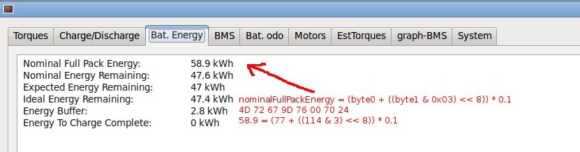
You are correct from that frame it is 58.9. I just stepped the code and my calc is correct, it seems it's my typing that needs more work in this instance :redface:
More strangely though as I went to double check the results, I grabbed a different log file and ran this through (one of the static logs I was using to find out cell voltages). This is where I really confused myself...
45 2A 98 E0 81 0 70 20 => which (and please correct me if I'm wrong) goes to 89.1kWh
This log and the first one, which was taken whilst doing a 0-60 run, are under two weeks apart. So I was VERY surprised to see such a large change. The biggest thing I can think of is that the cell temperatures are different between the two logs. The driving one had the cell temps around 16c, the static had them around 5c. I wonder if there is more to this statistic than meets the eye ?!�
Feb 16, 2016
pupik 89.1 is wrong
45 2A 98 E0 81 00 70 20 = 58.1kWh
hex 45 = dec 69
hex 2A = dec 42
58.1 = (69 + ((42 & 3) << 8)) * 0.1; ( all the values in a decimal form )
2 = 42 & 3
512 = 2 << 8
581 = 69 + 512
58.1 = 581 * 0.1
:smile: attention:
- on signed and unsigned type
- byte0 is left
- for hexa je writing 0x..
There is writing for 32bit C++
unsigned short int byte0 = 0x45;
unsigned short int byte1 = 0x2A;
float nominalFullPackEnergy = (byte0 + ((byte1 & 0x03) << 8)) * 0.1;�
Feb 16, 2016
smac Argh!!!! I really must double check my posts :redface::redface::redface:. Brainfutz meant I typed in the file name (89 was the % SOC of the log!) I'm obviously going mad
My C# code is similar (same) as your C++:
var nominalFullPackEnergy = (data[0] + ((data[1] & 0x03) << 8)) * 0.1;
Surprise, surprise, I too get 58.1!!
I guess the salient point is 58.1 < 58.9 from less than two weeks ago.�
Feb 16, 2016
pupik small wobble for parameter nominalFullPackEnergy is normal. My standard is +/- 0.2kWh
come back to you 58.9kWh soon, do not worry :smile:�
Feb 16, 2016
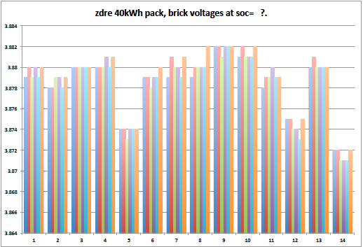
zdre parsed the data...
1 3.879 3.880 3.879 3.880 3.879 3.880
2 3.878 3.878 3.879 3.879 3.878 3.879
3 3.880 3.880 3.880 3.880 3.880 3.880
4 3.880 3.880 3.880 3.881 3.880 3.881
5 3.874 3.874 3.873 3.874 3.874 3.874
6 3.879 3.879 3.878 3.879 3.879 3.880
7 3.879 3.881 3.880 3.880 3.879 3.881
8 3.879 3.880 3.880 3.880 3.880 3.882
9 3.882 3.882 3.881 3.882 3.882 3.882
10 3.881 3.882 3.881 3.881 3.881 3.882
11 3.878 3.879 3.879 3.880 3.879 3.879
12 3.875 3.875 3.874 3.874 3.873 3.875
13 3.880 3.881 3.880 3.880 3.880 3.880
14 3.872 3.872 3.871 3.871 3.871 3.872
Total: 325.8 V�
Feb 16, 2016
pupik Message ID 0x0382 please
thx :smile:�
Feb 16, 2016
zdre From earlier post (different logging session though):
�
Feb 16, 2016
kennybobby i didn't have a chance to calculate the voltages from the previous data yet, but from your parse it looks like your pack is in great shape.
 �
�
Feb 16, 2016
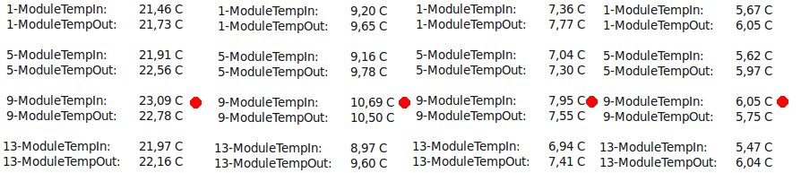
pupik Notice that the temperature at the module 9 is conversely
but for my car is the same :scared: ( but it's not always ) :crying:
I thought at first that anomaly is only in my car...
some idea?
 �
�
Feb 16, 2016
pupik Only my calculations ... :wink:
58 = 56.6 + 1.4
96.6% = 58/60
81.6 = 77.6 + 4
96.6% = 81.6/85�
Feb 16, 2016
garygid How often does the VIN appear on CAN3 ... perhaps once a minute?
In my TDC to OBD adapter for the ELM-type OBD dongle that TM-Spy uses,
I take ground and power from TDC pins 9 and 10, to OBD pins 4-5 and 16.
The CAN3 H, L come from TDC 1 and 6, and connect to OBD pins 6 and 14.
The wired female 16-wire molded OBD connectors that I ordered should
be here next week, and then I should be able to try TM-Spy Beta on my car,
and log multiple CAN buses simultaneously.
For logging systems like mine (that worked with the LEAF), I will probably connect:
CAN6 to the LEAF's EV-CAN pins, and
CAN2 to the LEAF's AV-CAN pins.
Then, connect CAN4 to OBD pins 1 and 9 ... unless others have better suggestions.
Do we know for sure which CAN bus is on pins 1 and 9 of the Tesla OBD connector?
Thanks, Gary�
Feb 16, 2016
zdre I am fully charged here. SOC says 69%
Battery temperatures were around 7�C
I am still trying to figure out what my degradation % is. Any idea of how to do that using these numbers?
The problem is that I cannot charge to 100%, so I cannot see the max charge.�
Feb 16, 2016
pupik and next story...
so, please forget to data from CANbus and calculated with me:
assuming for same cells...
7104 / 5880 / 5040 = 85 / 70 / 60
so ratio ca. 84
TS60 5040 = 84 * 60
TS70 5880 = 84 * 70
TS85 7140 = 84 * 85 -> 7104/7140 = -0.5% (only -402W from 85000W)
TS90 different chemistry ... ???
I calculate it wrong? :wink:
thanks�
Feb 16, 2016
smac Only thing I can think of is to take the nominal full energy figure (56.6) and see how it compares to a fresh pack.
Now my 60 is 18 months old with 12.5k miles on the clock and shows 58.1. (So newer but not fresh)
BUT Mine is a "B" pack, and I assume yours is an "A". Also the energy buffer figure is different
If you can find another 40 owner maybe you could make a fairer comparison?�
Feb 17, 2016
markwj For a while now, we've been making DIAG connectors for OVMS on the Tesla Roadster. I notice that some guys here are using those in Model S now (even though only 1 CAN bus is wired).
I'm considering getting some fully wired connectors made for my own use. The same as the existing OVMS cable (https://www.fasttech.com/products/0/10000001/1000400-ovms-data-cable-for-tesla-roadster-1-x-2-x), with the same DIAG plug, but with all 12 pins cabled. Perhaps 1m (3feet) of open ended cable on the end. Something easy to solder on to a DB9 (or whatever is required).
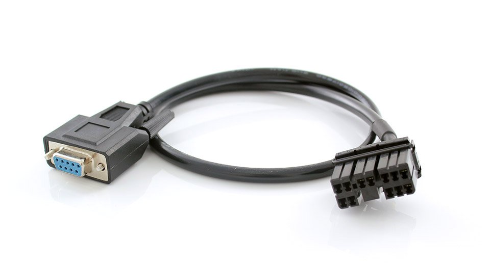
Would that be something useful to the community here? If so, I can easily get them to make up a batch. Is 1m cable enough? Cut and pre-tinned for soldering useful? Any other suggestions?�
Feb 17, 2016
kennybobby 69% of nominal 56.6 + 1.4 buffer = 40.02 kWH vs expected remaining of 40.8
Also look at nominal remaining vs expected remaining: 39.2 vs 40.8
edit
Looks like very little degradation by either of these comparisons.
336.5V was under charging, so use the other reading.
326 V / 84 = 3.881 volts per cell at 69%, now that agrees with the brick voltages you measured.
add this to Simon's data
69% ~ 3.881 V
79% ~ 4.09 V
89% ~ 4.179 V�
Feb 17, 2016
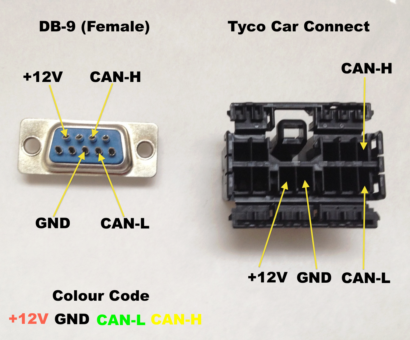
garygid markwj,
We could use a very short TDC to female OBD adapter cable, with CAN3 wired
to OBD pins 6 and 14, and power and ground, of course.
We have AVR-CAN based loggers, with DB9 input that might use your TDC to DB9
cable, depending upon the pins used. What is your DB9 pinout, please?�
Feb 17, 2016
obrien28 Gary,
I realize that you are probably trying to reuse existing hardware but the size of an OBD-II connector compared to the TDC is enormous, think it might be more worthwhile to interface directly with that, even if requires some soldering, it would be pretty easy to desolder the male OBD on the Leaf Spy and in the same through holes solder wires leading to a male TDC, no funky adaptors or long cabling required, you might even be able to tuck it into the back of the cubby. Tesla's CAN bus structure is significantly different than the leaf with much more interconnection of the various systems through gateways (unlike the leafs EV bus and AV bus). The real high value targets are CAN3 Powertrain (battery, drive unit and chargers) CAN6 Chassis (TC/ESC, body control module, ABS, EPB, TPMS) and finally CAN2 Body (lights, locks, windows, sunroof, radio etc). CAN4 is a fault tolerant module for the seat modules, PTC heater, and RCCM not much interesting going on there for most peoples purposes.
As for what pins are brought out to the OBDII port. To make a long story short the only thing available that we would care about is 12V and GND plus the CAN6 chassis bus, not of interest for our particular application.
More details:
1 = CAN6+
P4 = GND
P5 = GND
P6 = CAN1+
P7 = K/Ser line
P9 = CAN6-
P14 = CAN1-
P16 = Battery Voltage (nom 13V)
CAN1 is a special bus that connects directly to the center console stack and nothing else, what it's used for is anyones best guess at the moment (diagnostics or firmware loading?). The K/Ser line connects directly to the RCCM (remote climate control module) and is (I'm guessing) some kind of LIN interface, the TDC under the center console taps off this line and connects to P3 of the diag connector.
Also the VIN is on ID 0x508, not sure what the rate is though.
- - - Updated - - -
Mark,
I don't know if it would be a better solution (it has worked for my needs reverse engineering) is a TDC to ethernet cable, with that I can go into a standard Ethernet to DE9 adaptor and then connect the DE9 cable to things like the CANtact or Kvaser Leaf Light (the reason I built it), it is a little bulkier but it enables the swapping of different buses just by changing out the Eth-TDC cable and keeping the same interface on the DE9 end, meaning I can have any bus without re-wiring on my logger.
Probably too bulky for stashing under the console but food for thought, I'll try and get some pictures uploaded later.�
Feb 17, 2016
zdre 336.5V was not an accurate number as it was still trickle charging because of HVAC. The total voltage was 326 when not charging.�
Feb 17, 2016
TheBlackKnight I'm pretty sure that the rate is actually every 5 minutes - no joke. The interval is so long that I've got a whole lot of captures that never got any 0x508 messages. Apparently the car doesn't expect the VIN to change that often. :wink:�
Feb 17, 2016
Kalud It looks like its 5 min (300 sec).
Looked at earlier logs
timestamp
1435778984.63
1435779283.96
delta
299.3299999237�
Feb 17, 2016
smac It would be interesting to know if this is 300s on a regular "heartbeat", or if it is bumped on the basis of another message on the bus. (for example plugging in to a SpC)�
Feb 17, 2016
Kalud This was from a log while driving. I'll have a look more into it.�
Feb 17, 2016
TheBlackKnight Yes, it seems to be a 5 minute heartbeat message that is sent any time the car's computer systems are operating. I've seen it on driving captures (but only captures that are minutes long, otherwise you're likely to never see it). I can't really be sure as to *why* it sends its own VIN number every 5 minutes. Who is listening for that message? The VIN never changes. Maybe some components check the expected VIN number and fault if it does not match - sort of like how radios and transmissions have been tied to the original vehicle in many cars. But, I haven't seen a device that seems to care. So far I've heard of people using drive trains and chargers outside the car and they seem to work without any VIN number communication. I wonder if they'd fault if they got the VIN message and it didn't match their expected VIN? Anyone brave enough to try this?�
Feb 17, 2016
markwj I have a few manufacturers across the border (I am in Hong Kong) that I have worked with in the past for custom OBDII cables. Simple to get this done, but the TDC pins and plugs (Tyco) are only available in China in 10,000+ quantities, so need to provide those to them directly. I think the way to do it would be to get the manufacturer to provide their standard OBDII socket and cable (something they are very familiar with), and then customise the TDC end with the four pins required. MOQ is usually around 50 pieces.
We used the pinout that was popular at the time on a couple of different USB-CAN loggers:
If the non-TDC end is open, anything can be put there. The wires should be compatible with ethernet connectors, and it is a couple of minutes job to crimp those.
I know what Tesla used to do (on the roadster) is bring out the connector onto three separate DB9 connectors (one for each bus). That is great for a single-CAN-bus logger as you can just plug into the bus you want, but not so good for those loggers capable of logging multiple buses at the same time.�
Feb 17, 2016
wk057 Digikey has the connectors and pins for the Tesla CAN diagnostic connector... I'll dig up a part number tomorrow�
Feb 17, 2016
garygid For comparison, are these the correct TDC-mating items from Mouser?
The Q1 price is $2.42 for this connector:
Mouser Electronics - Be back soon...
and $0.13 each for pins, up to Q99:
Mouser Electronics - Be back soon...
Cheers, Gary�
Feb 17, 2016
markwj We purchase these for OVMS (and they work fine in the roadster):
Mouser Electronics - 173851-2
Mouser Electronics - 173631-1-Cut-Strip
There is also:
Mouser Electronics - 173631-1 Reel
if you like to go with big orders ;-)�
Feb 17, 2016
pupik for EU boys connector here... :wink:
Farnell - 173851-2
Farnell - 173631-1�
Feb 18, 2016
Turbo3 I have a 20 minute trace that shows the VIN coming out every 5 minutes with only a 7 msec variation.
Also SOC frame 0x302 always has 8 bytes of data whereas wk057's excellent document lists it as having 3 bytes. Typo perhaps?�
Feb 18, 2016
CHL Doe's this curve only obtain with battery heater or during charge ?�
Feb 18, 2016
TheBlackKnight Not a typo. At least in older firmwares for US cars this frame has three bytes. It is possible that they changed it in later firmwares or for a different market or something.�
Feb 18, 2016
Kalud That 530 seconds (~8min) is unplugged, range mode OFF, pre-heating the cabin (and pack). Showing the cells min / max temperatures.�
Feb 18, 2016
apacheguy Active heating only applies under 2 C. Why does yours seem to climb over 8 C?�
Feb 18, 2016
Kalud I see Tmin (minimum across all the 32 temperature sensor) slightly above 2C but still < 3C. Looks fine to me.�
Feb 19, 2016
CHL So 30' of battery heating is enough�
Feb 20, 2016
markwj Replying to myself, I just put in a mouser order for 1,000 pins.
�
Feb 20, 2016
obrien28 I finally received my Particle Electron (cellular enabled dev board running on the ST32 micro) in the mail yesterday, looks like it could be promising as a totally wireless logger, I have to experiment with their CAN library (the ST has a built in controller so all that's needed is a transceiver to deal with signaling) unfortunately I'm heading off for vacation soon so I might not get a chance until I get back, news from the frontline to follow ASAP.
As they say, keep calm and carry on...�
Feb 21, 2016
apacheguy Bump. Can anyone answer this? Under what condition does the BMS set a passive cooling target of 52 C in an S85 (S85 = No max power mode)? Is this with range mode?�
Feb 21, 2016
wk057 Good question. I haven't had time to map the temperature targets to various conditions. So far the only time I've seen a passive target that high is with max battery power on the P85D.�
Feb 22, 2016
garygid Do we know anything about the Tesla Diagnostics Connector in the Model X?
Where is it located, pinout the same as the Model S, etc?
Anybody tried finding and logging the Model X "powertrain" CAN bus?
What is on the Model X OBD connector?
Thanks for any help.�
Feb 23, 2016
smac Just tried to grab a log from an EU 70 and 90...
Different connector�
Feb 23, 2016
wk057 You sure? Pics?�
Feb 23, 2016
smac On phone.. can't get upload working. Sent you an email�
Feb 23, 2016
wk057 Definitely interesting. It's close, but not quite the same connector. Very odd. I have never seen one with a different connector, and I've seen an EU on before as well. I also didn't see any different tool for this connection in Tesla's online service manual last I was on there, either. So, I'm confused for sure.�
Feb 23, 2016
Ingineer All cars I've seen made since about September 2015 have a new connector.�
Feb 23, 2016
smac Had a 3rd attempt, this time a November delivered 90D, again same thing
So despite my best efforts to get some logs from a fairly exhaustive set (70S 90S and 90D) all have failed. Might be a RHD difference ?.
Along with the different blue connector, there was also a small white connector:
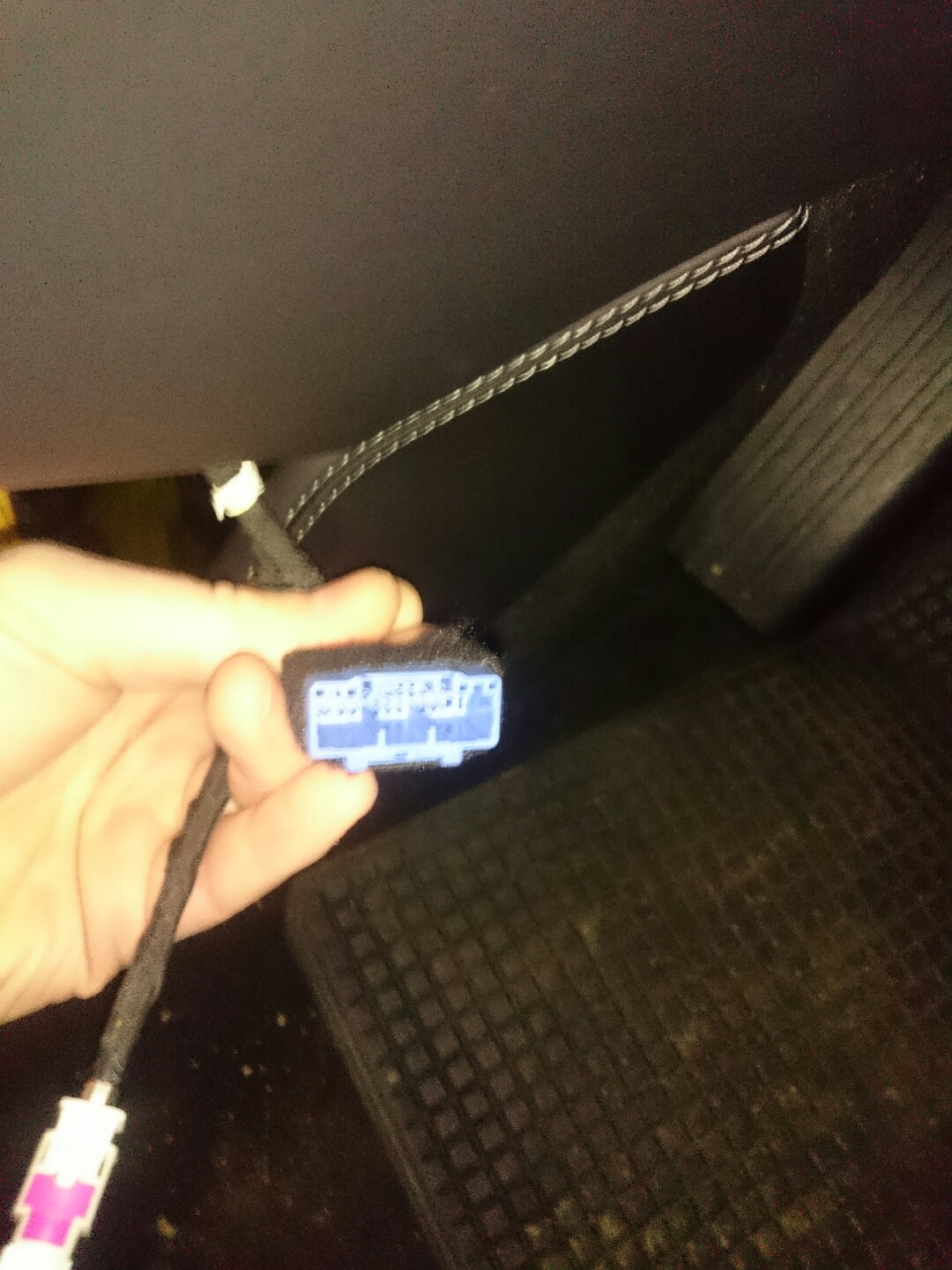 �
�
Feb 23, 2016
smac Interesting.
Certainly born out by my findings if this isn't a RHD market thing.
Quite what the motivation is to change the plug escapes me, surely it will make it harder for the Tesla techs ?? Maybe they needed another bus for the X and there are more pins? (But I'm clutching at straws here!)�
Feb 23, 2016
Andyw2100 Is it possible Tesla could make some sort of connector for the techs that actually fits both types of connector (has backwards compatibility) in which case the change in the connector wouldn't really be an issue at all for the techs once they had whatever new part they needed?�
Feb 23, 2016
kennybobby Not even close--not a chance...�
Không có nhận xét nào:
Đăng nhận xét