Jan 11, 2014
LastNLSig DIY for BlackVue 550 installation (front and rear camera).
Constant 12V power source from the dash:
First task is to make a connection to constant power supply (if you want the camera to be in constant operation also when parked). As has been mentioned on this forum the power can be tapped from the glove box fuse. (likely this is one of the rare functions that is always on; must be the reason to have a separate fuse for one single led).
It has been shown before on this forum that power can be tapped directly from this fuse. But this involves bringing a lead back into the salon thru the firewall. I figured that there should be an easier way to obtain the same result. Why not tap from the glove box itself.
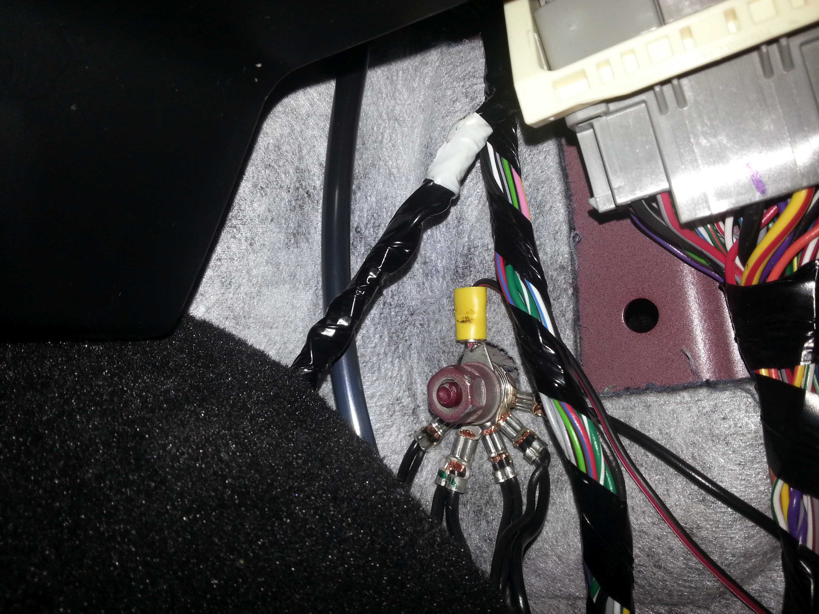
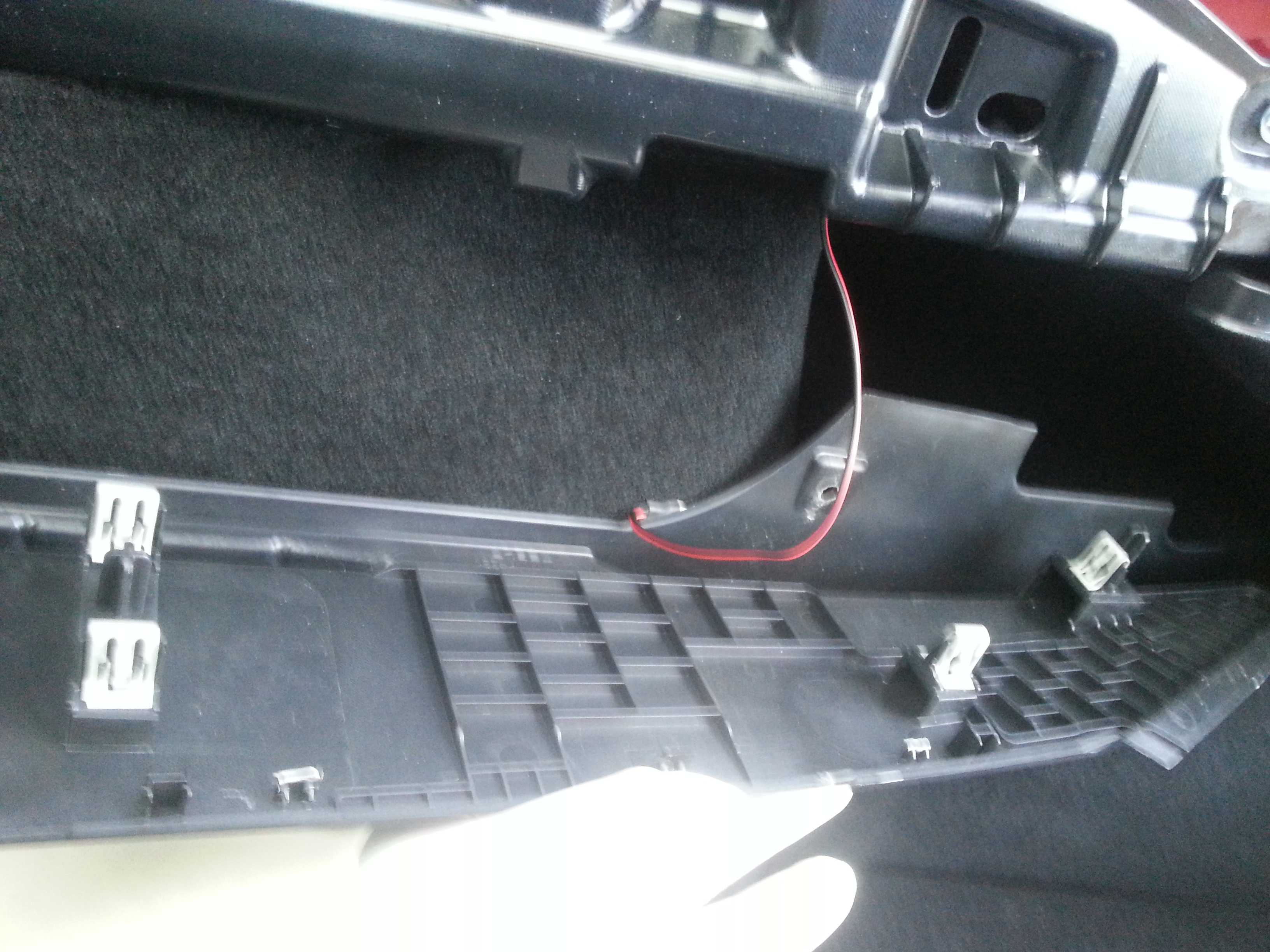
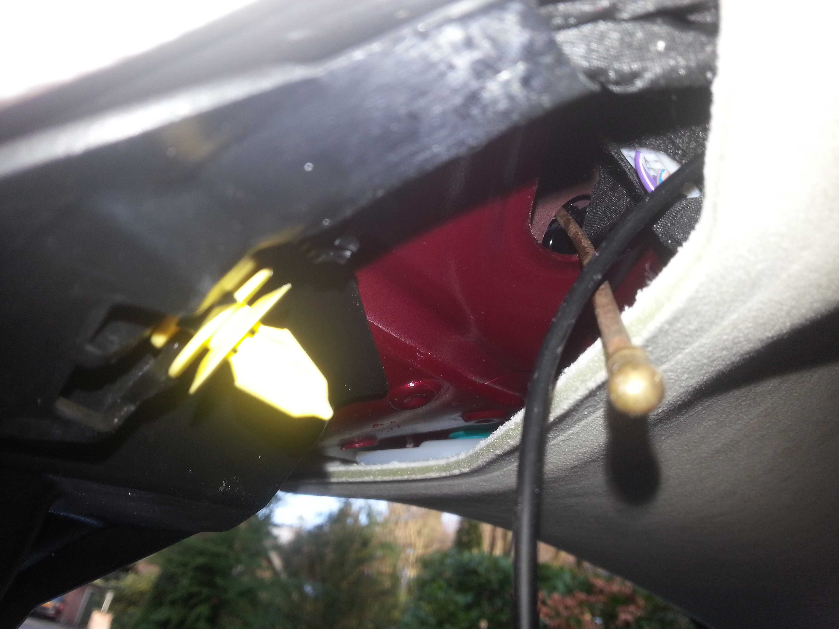
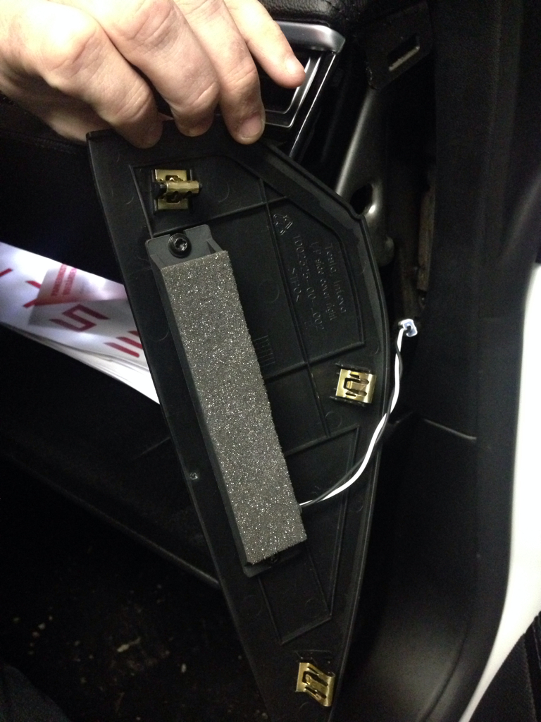
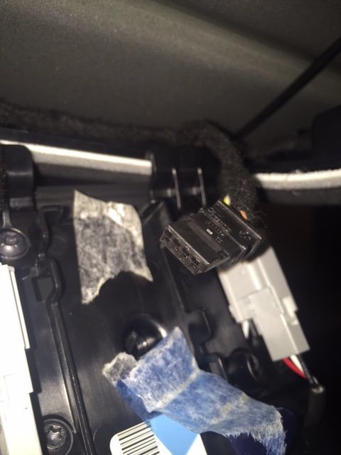
To do this, open de glove box. Prise out the larger lining piece that holds the LED (not the light itself, but the whole frame). You now see this:
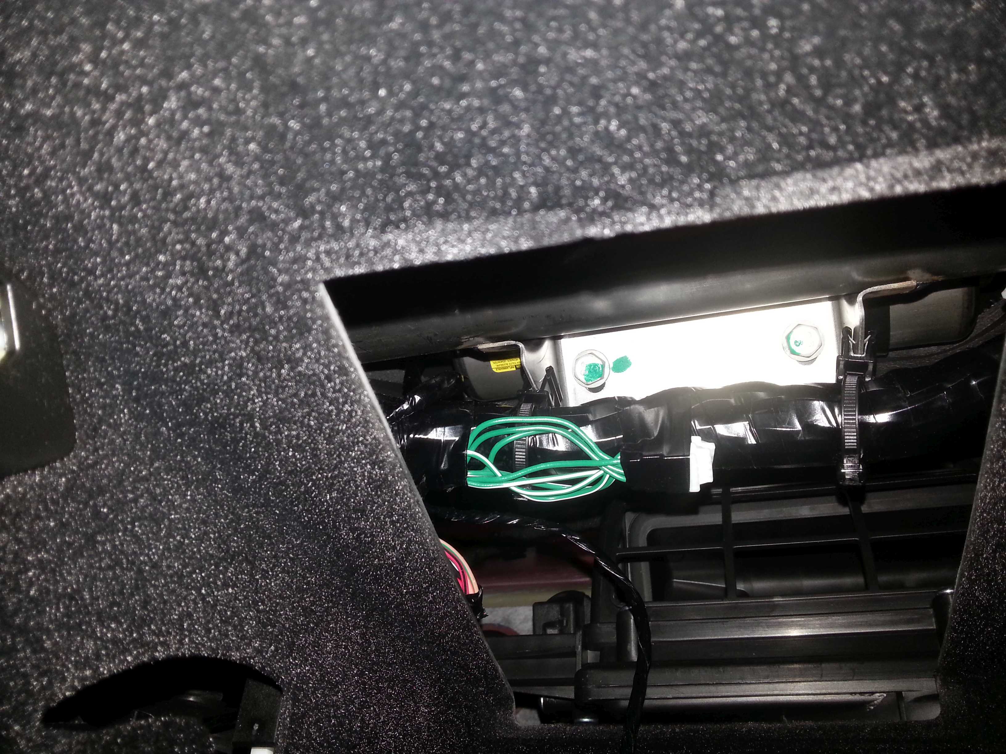
The glove box light itself is not constantly powered of course (red/black wire). Its power supply is via a switch on the left hand side (red wire switched to the red/black wire for the light). From the switch I traced back the wires. On the left hand side just above the switch is a small bundle of wires that includes the red and red/black wires.
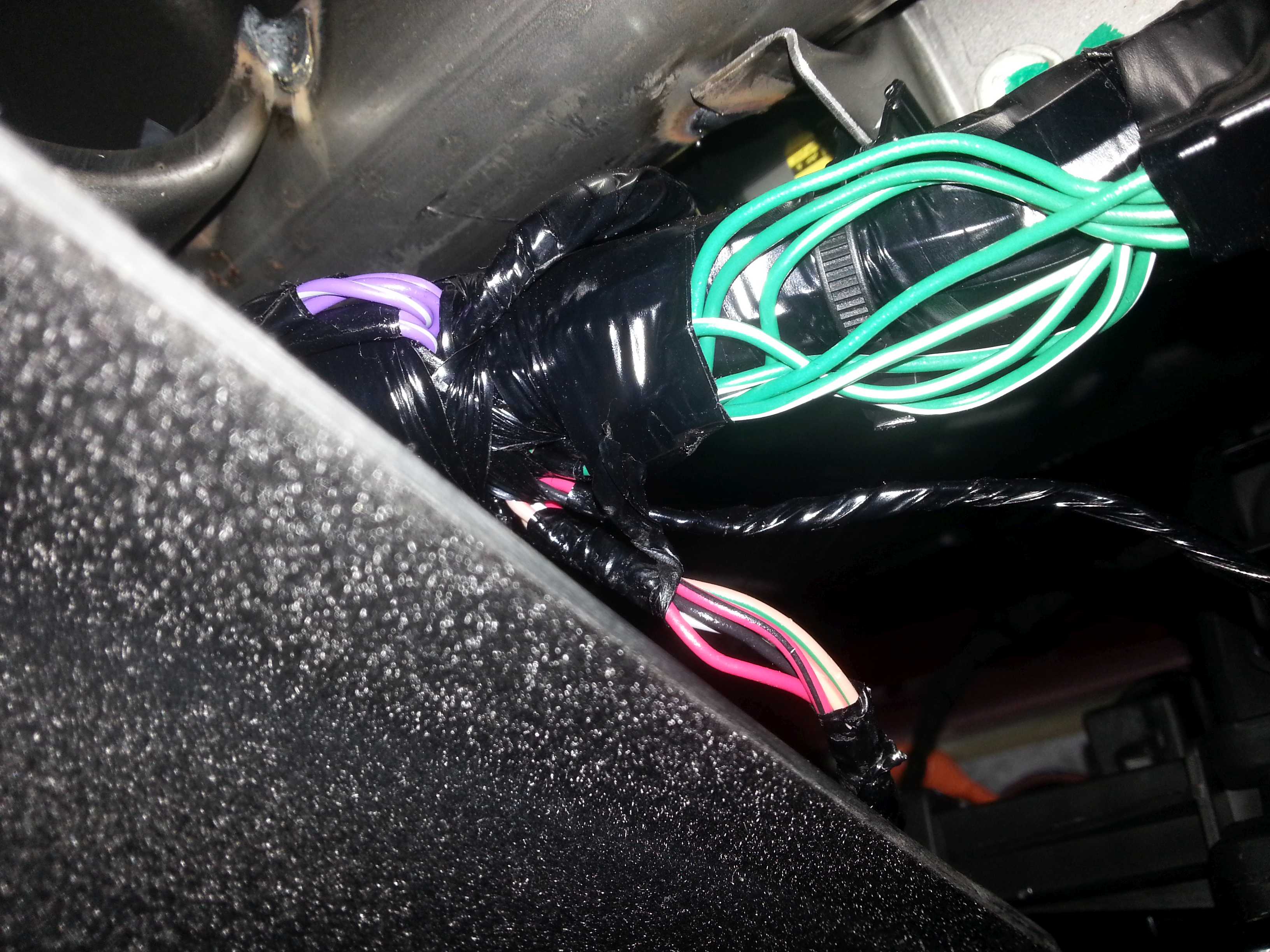
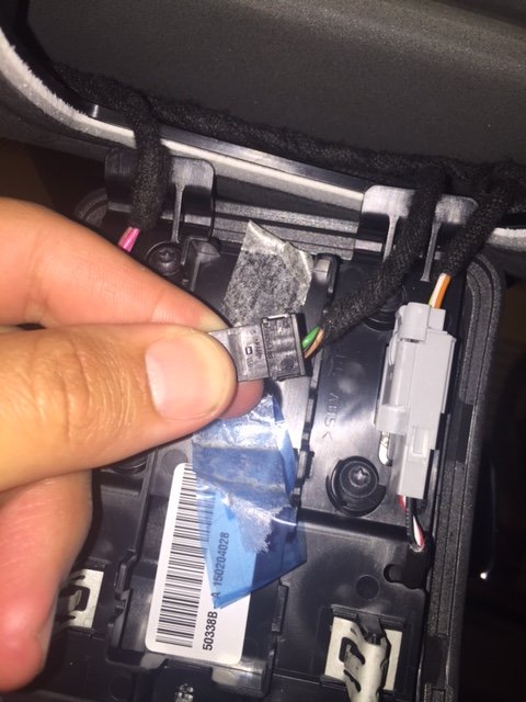
Remove some of the tape to get sufficient access to the red wire, like this:
(I actually removed some more tape on the right hand side to get access to sufficient length of red wire to be able to clip the non-solder connector on)
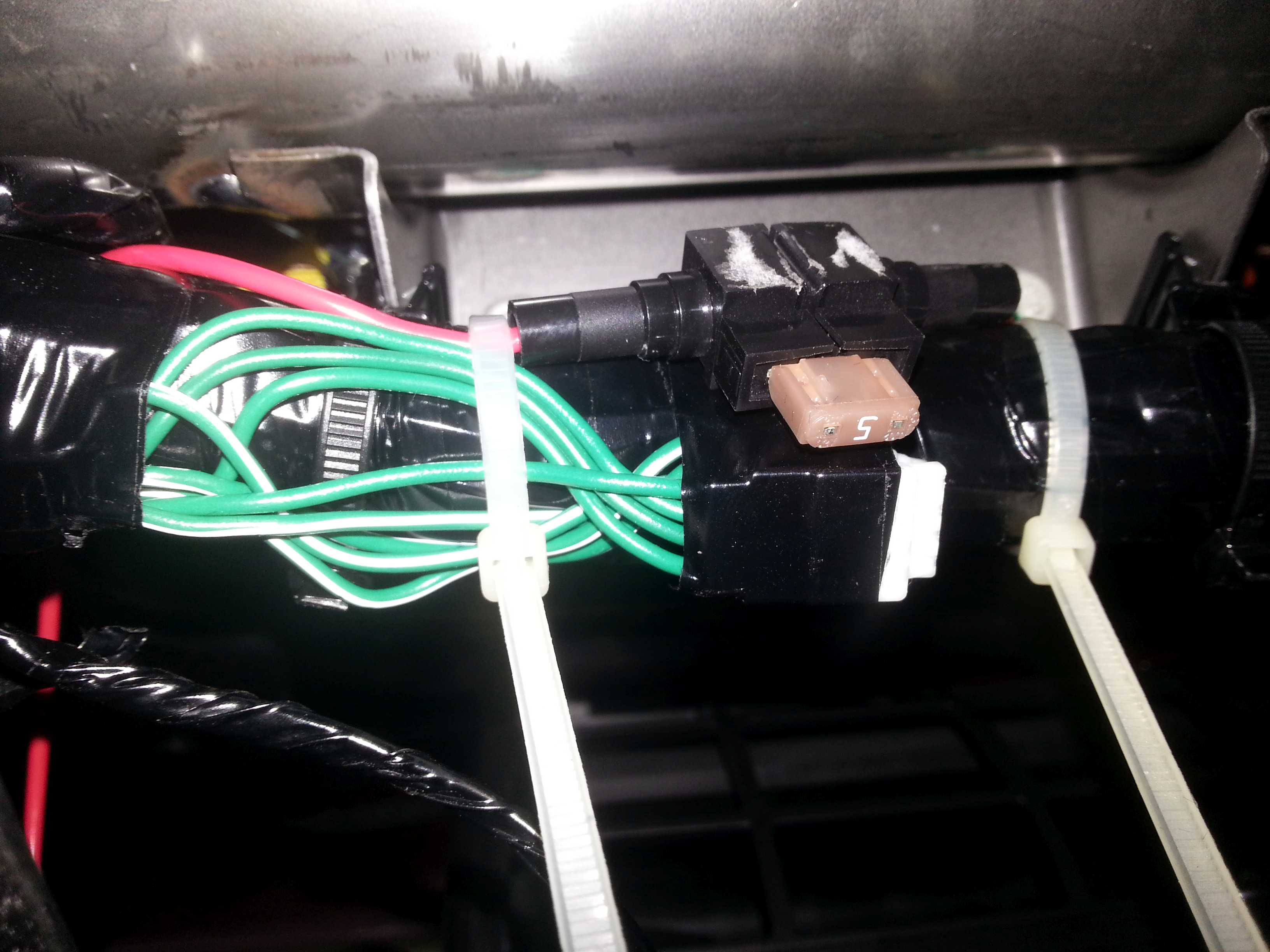
I prepared a wire with a fuse as power line for the BlackVue. Few inches on one side, enough length on the other to make it to the right side of the car. This extra fuse is somewhat superfluous as the camera is only sharing the original fuse with the glove box led. I have not found a 2A fuse of this type yet (do they exist?). 2A would be nice (behind the 5A in the fuse box). The original power cable for the BlackVue also has a 2A fuse but I cut that one off to be able to lead the wire thru small holes.
Clip/join the wire with the red wire. I hate these clips but safer bet than soldering (too high risk of collateral damage in this location). I demolished the outer clip somewhat so I put some additional tape around it:
I tied the fuse holder against the thick wire beam so that direct access to the fuse is obtained when the glove box light is removed. To me this was the best option for easy access, rather than removing the side panel of the dashboard (tight clips; possible damage) or having the fuse behind the mic frame in the roof lining (also easy access but easy to stain the roof lining).
Now it is time to open up the right side of the dashboard. Unfortunately I did not make to many pictures at this stage of the process.
You need to:
Remove the cap on the side of the dashboard. It holds with 3 clips. These clips are used a lot in the car and are rather easy to release (without the feeling you are breaking something), however in this case, since there are 3 so close together, it did not feel very comfy prizing this piece out.
Remove the doorstep cover. Just start pulling upwards. Came out rather easy. By removing this piece you get access to a lot of wiring on the right side of the foot well.
Remove the little black plastic piece between the dash and the door (no clips)
Working from the access in the glove box you can now push/pull the power lead over the glove box to make it exit the dash on the right side. If your hands are small enough you can tie the wire to other wires/fixtures to prevent it from jittering.
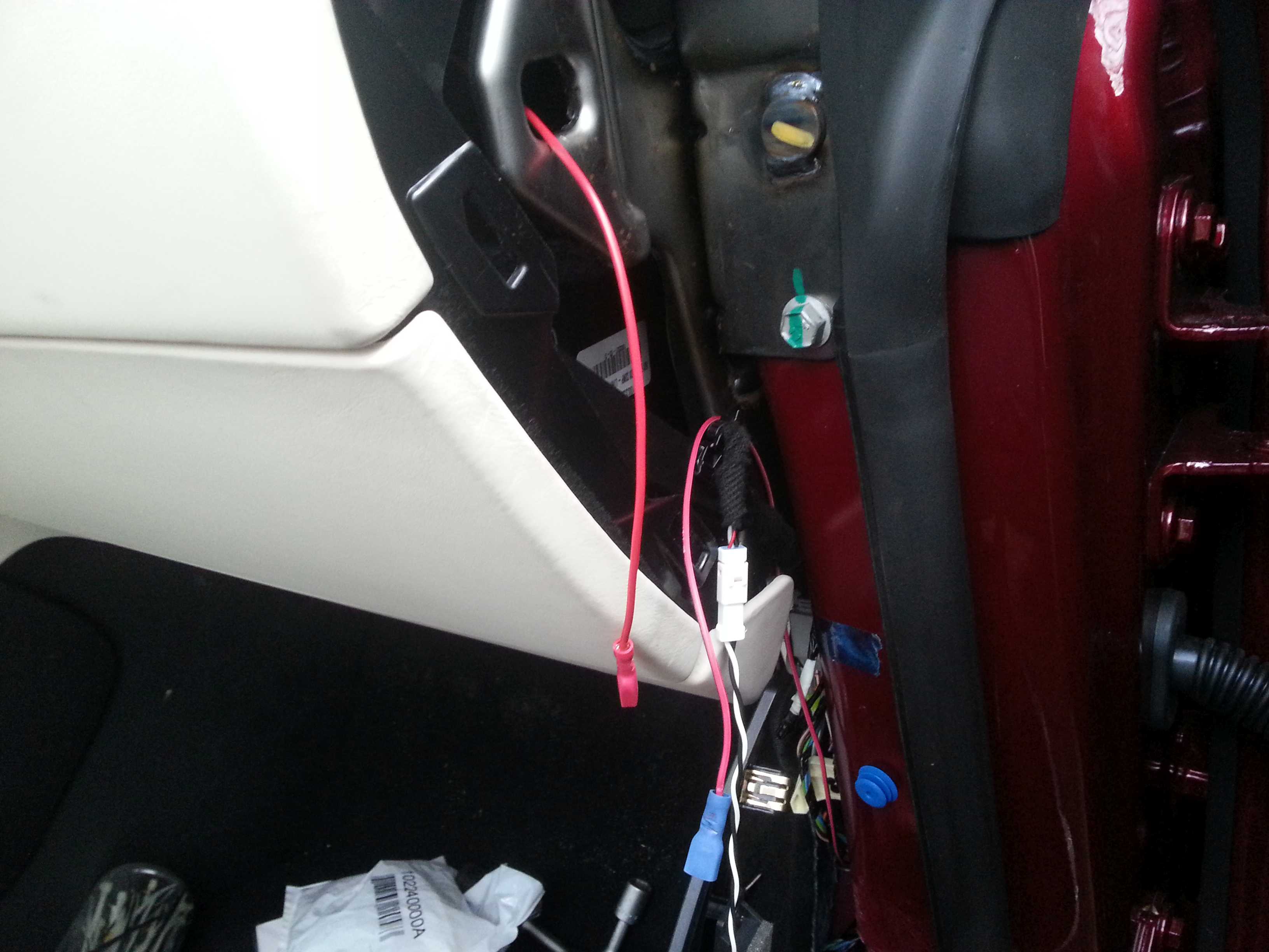
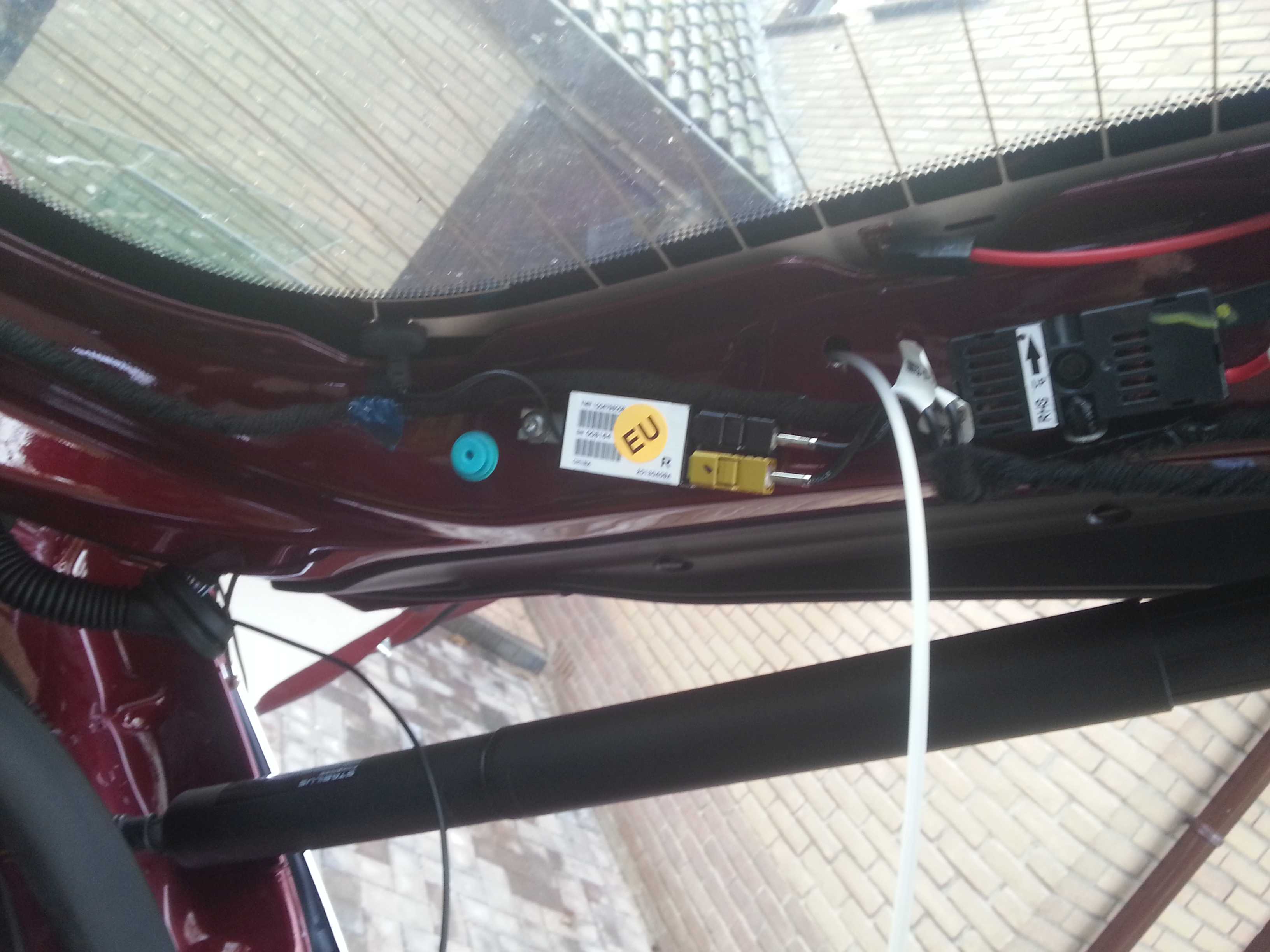
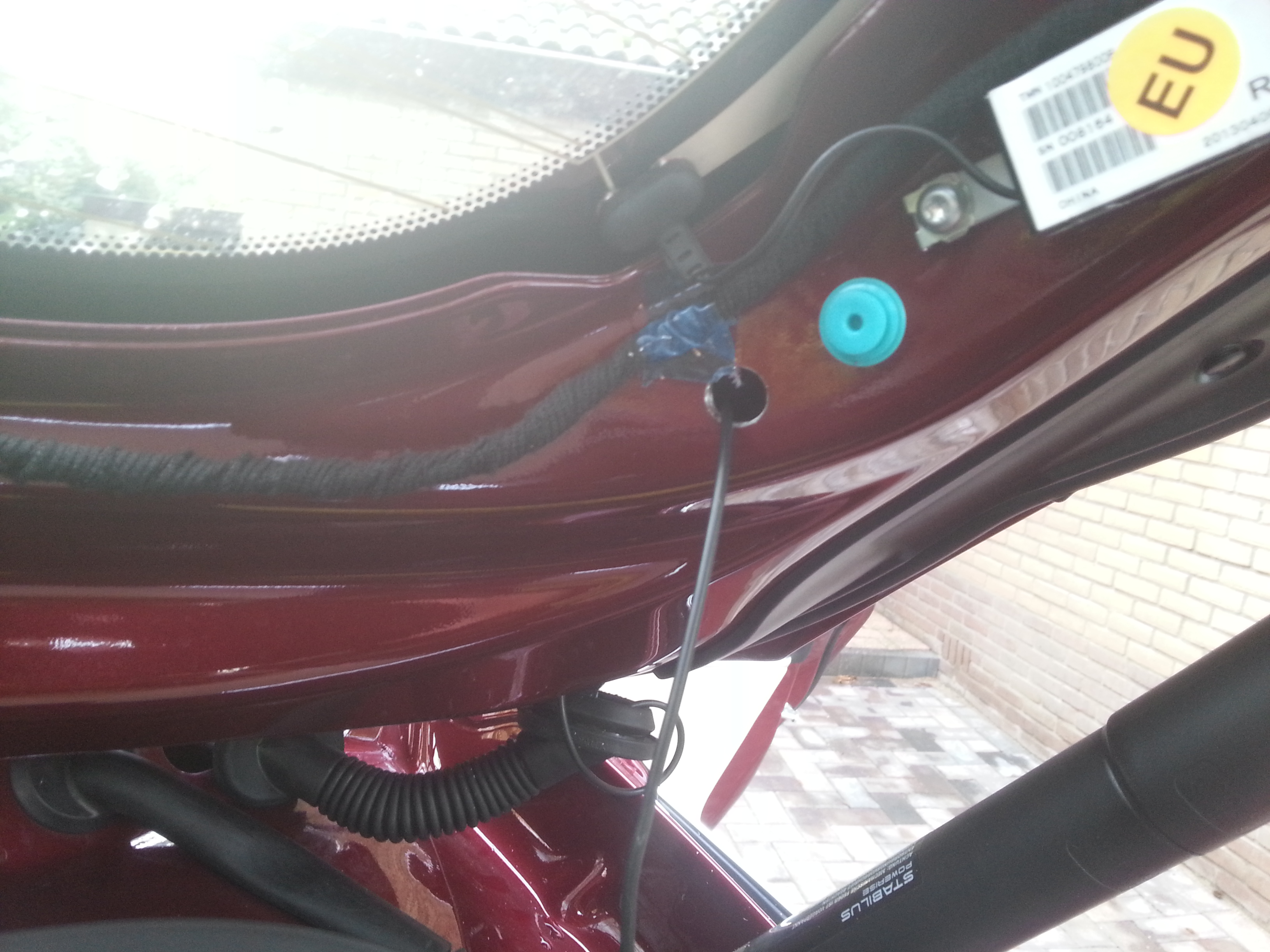
Connect the negative ground wire to the frame of the car. This point is found on the right side of the foot well (the yellow ring is mine, the wire should have been black, but I only had red/black available):
Lead the wire up to the side panel of the dash.
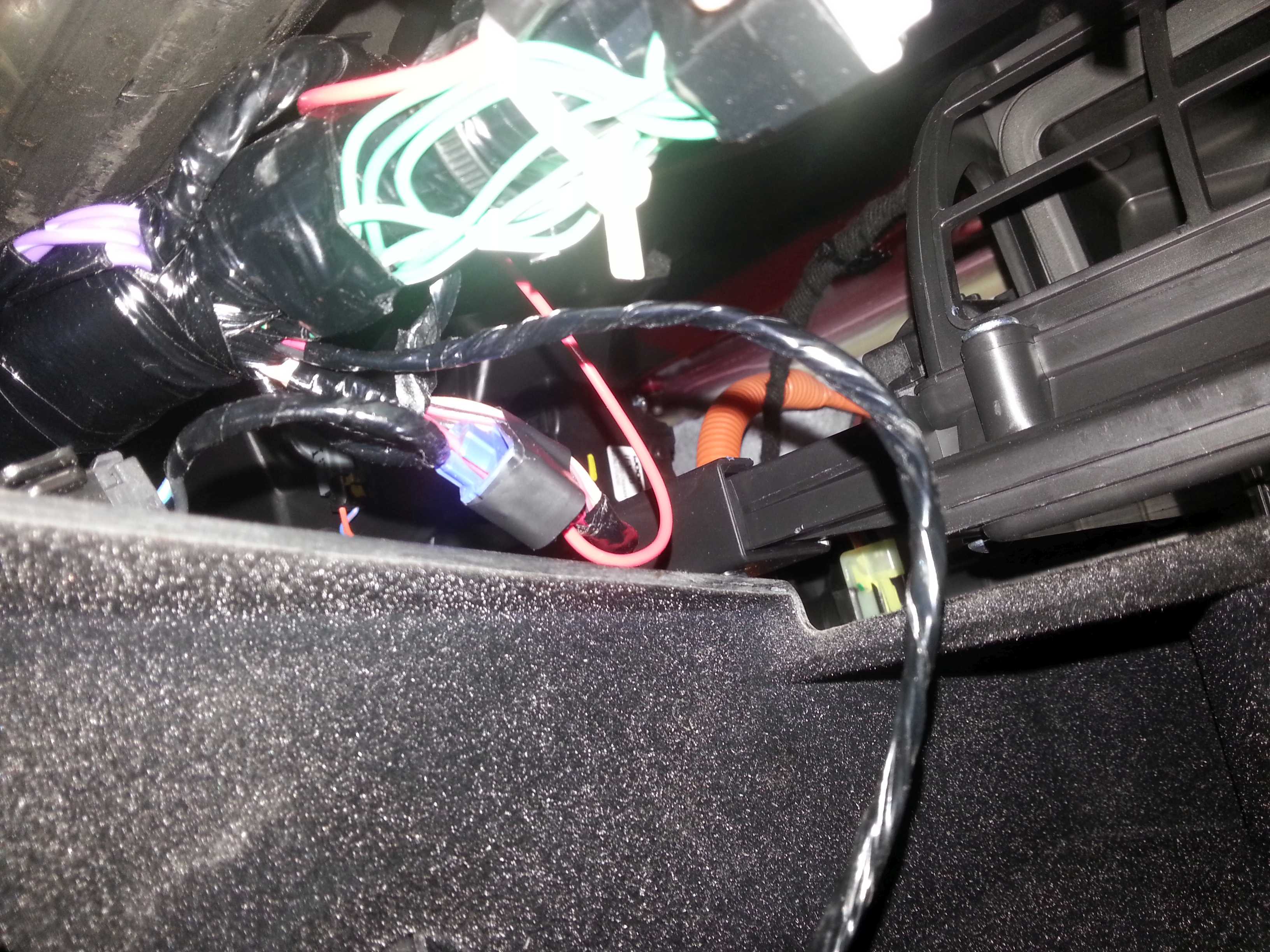
I decided to make the terminal for the power connection here (red and blue connector). Decent accessibility and still useful for possible future connection of other applications in the dashboard area.
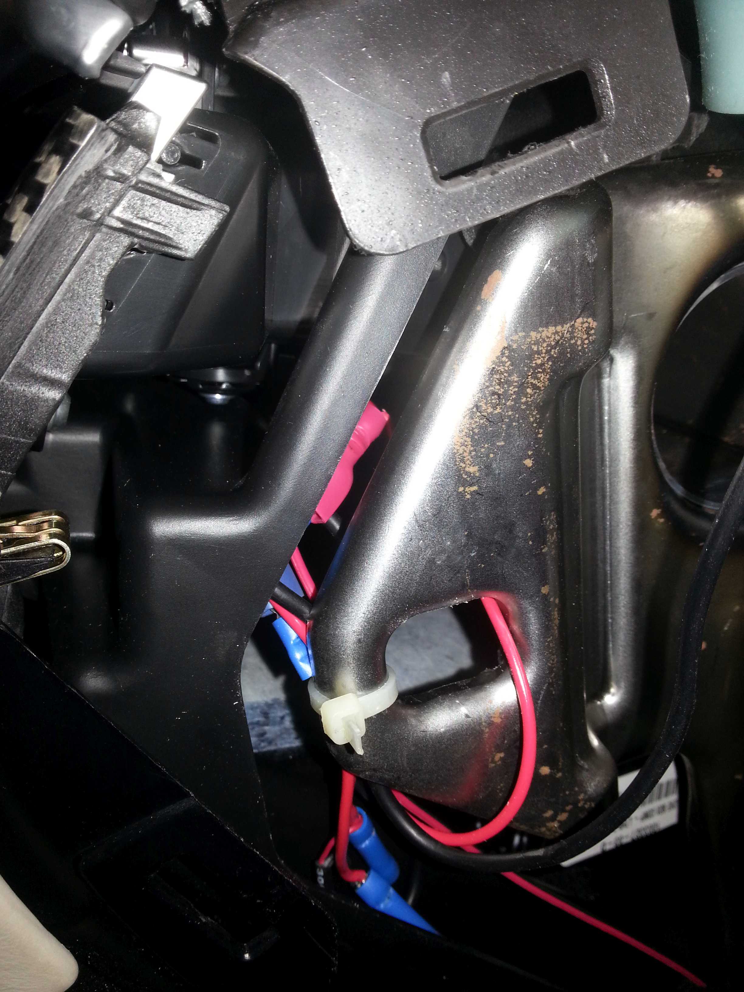
After connecting the power cable from the camera I tied it all up behind the dash frame:
Wiring for the camera:
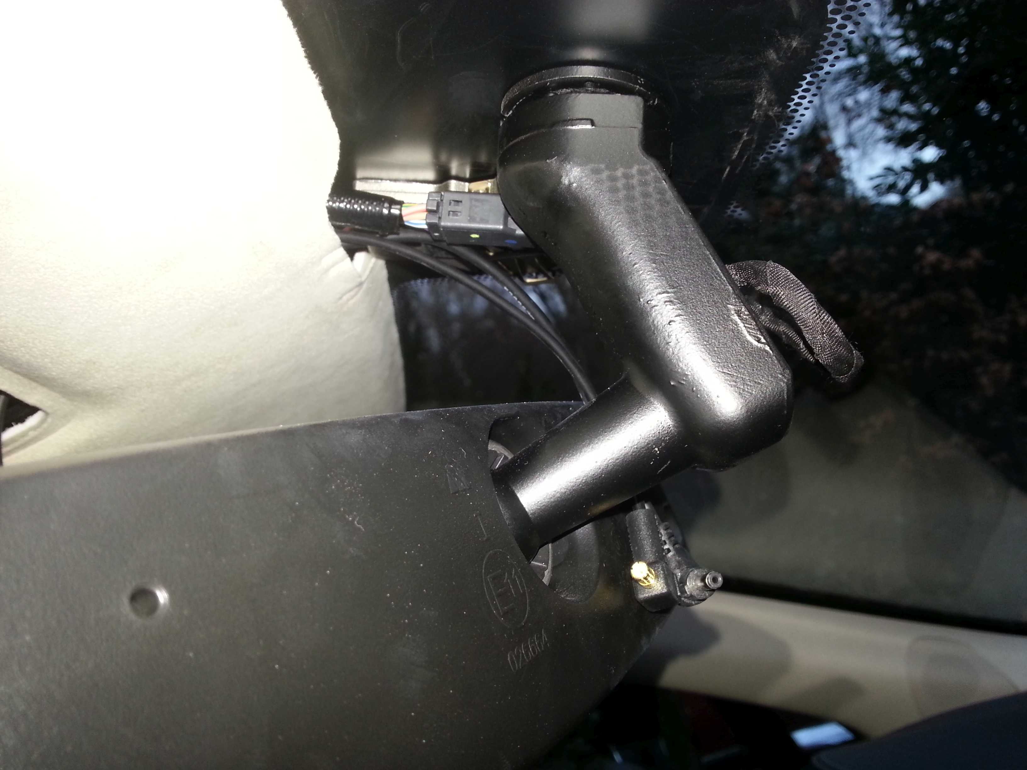
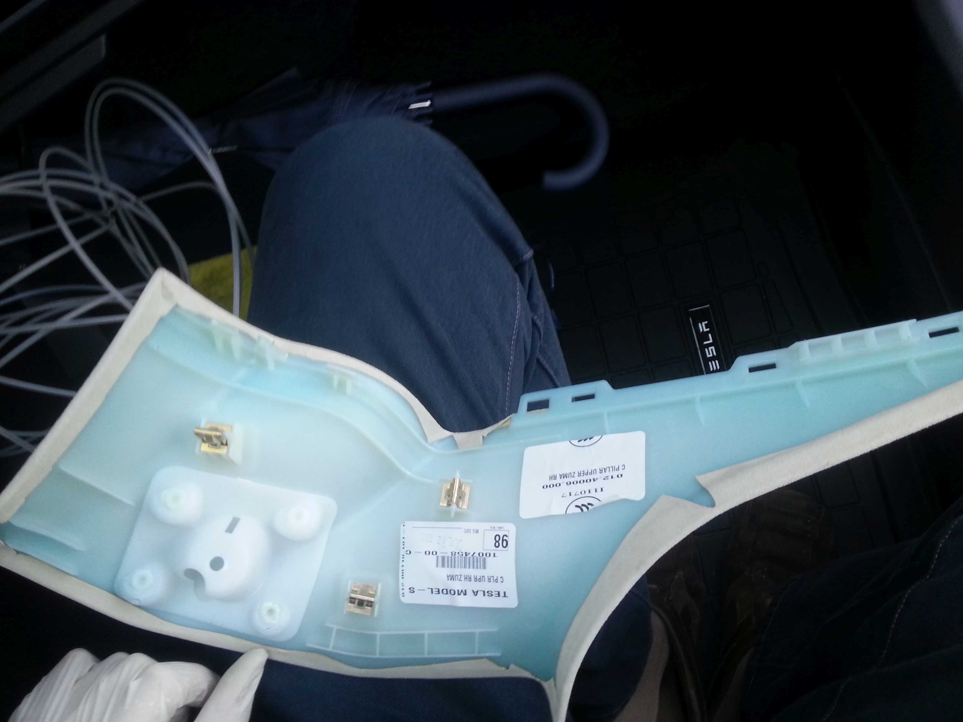
Remove the microphone frame in the roof lining
Remove the black cover around the rear mirror mount. This piece comes off in two halves. Gently pull them apart. Not a nice piece, feels like some clips might break off. So be careful.
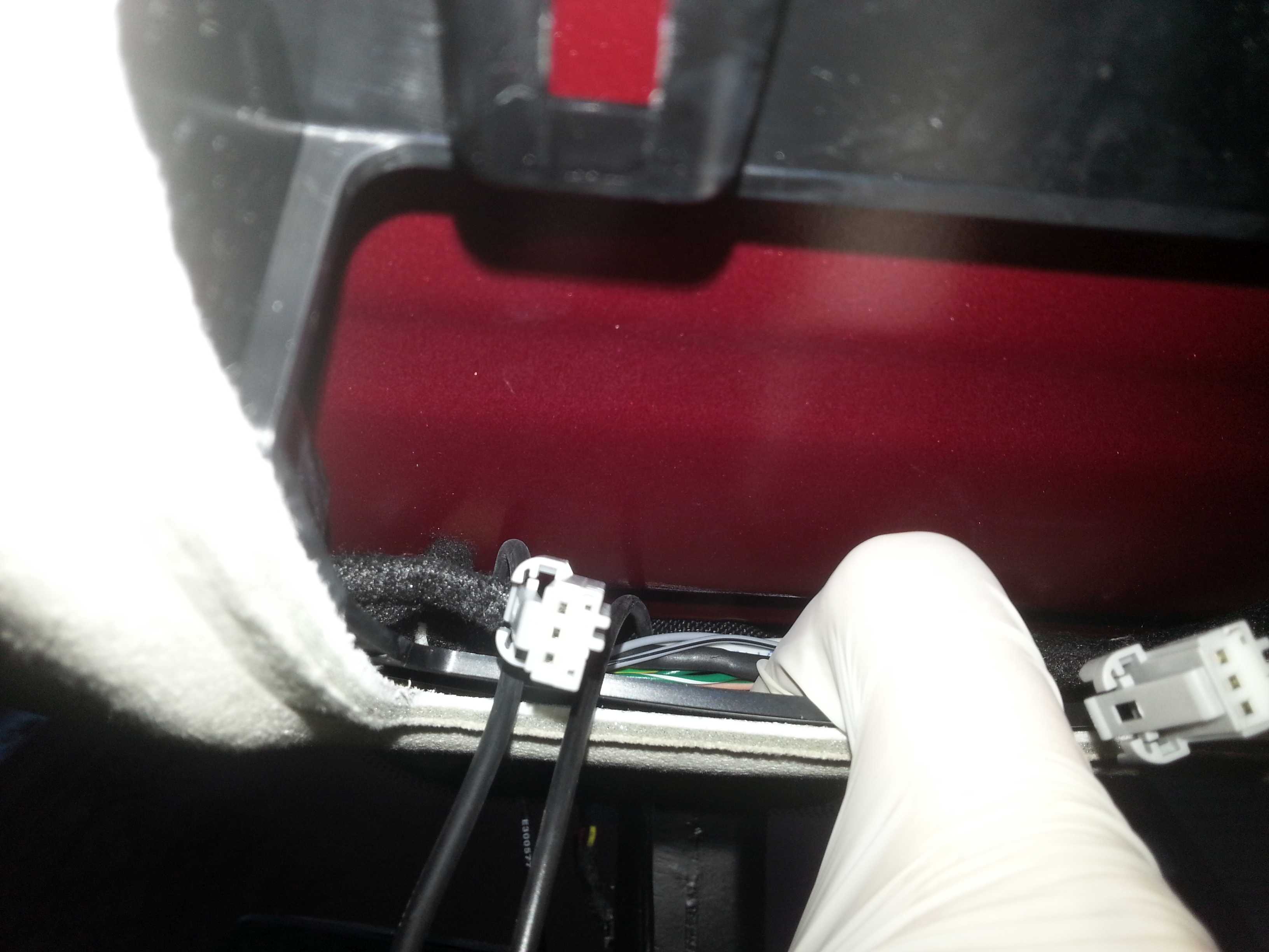
Push the roof lining down a bit and feed the cables/connectors thru parallel to the other wiring. (the white piece in the pic is my gloved finger).
At this point I have to remark that I have a pano roof which makes live a lot easier to install the cables.
Again at this point not too many pictures.
From the hole in the roof lining, bring the cables backwards to come out on the pano roof side. You will notice that there is a lot of space between the roof lining and the pano roof. You can easily slide your fingers in between.
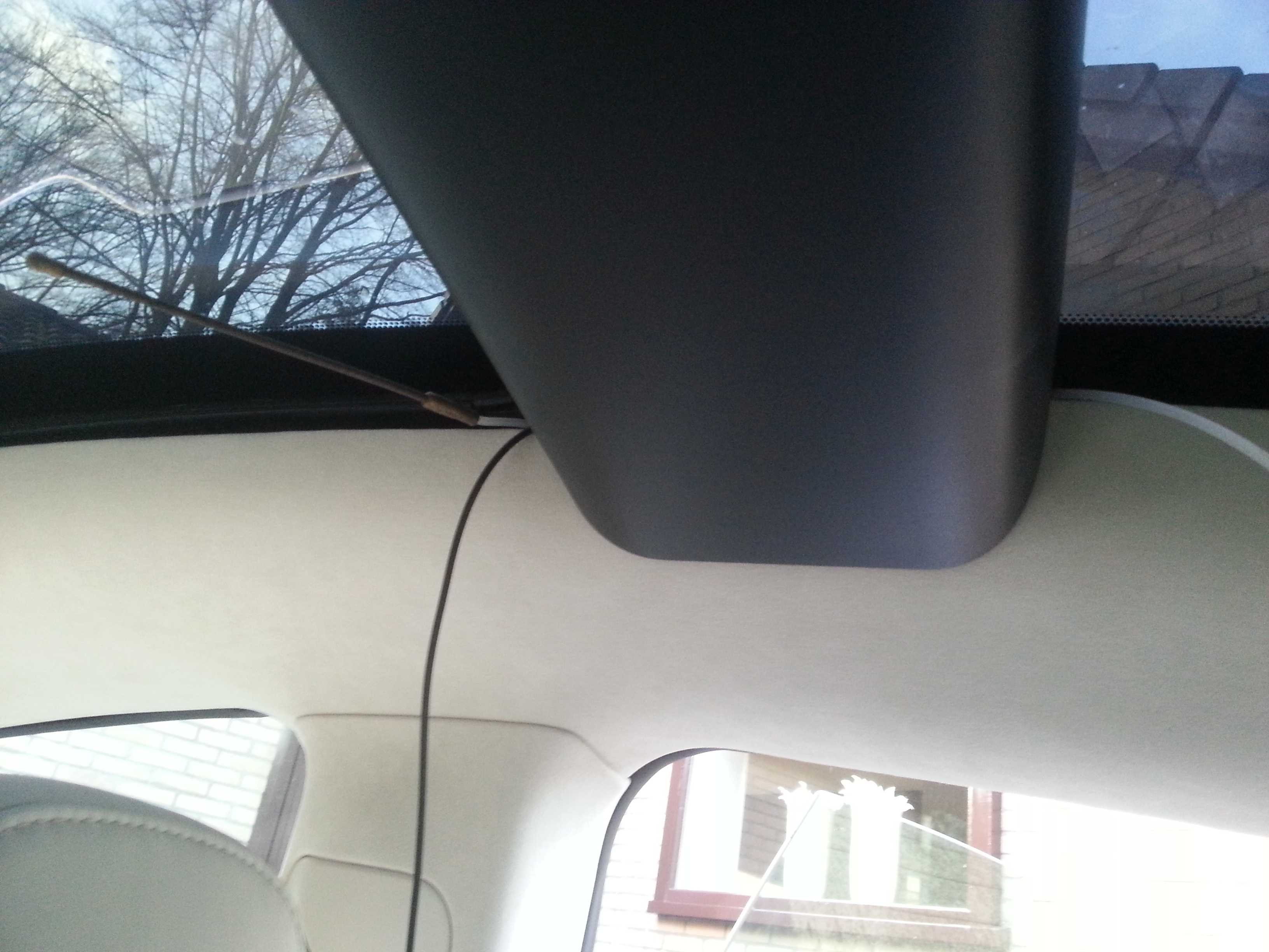
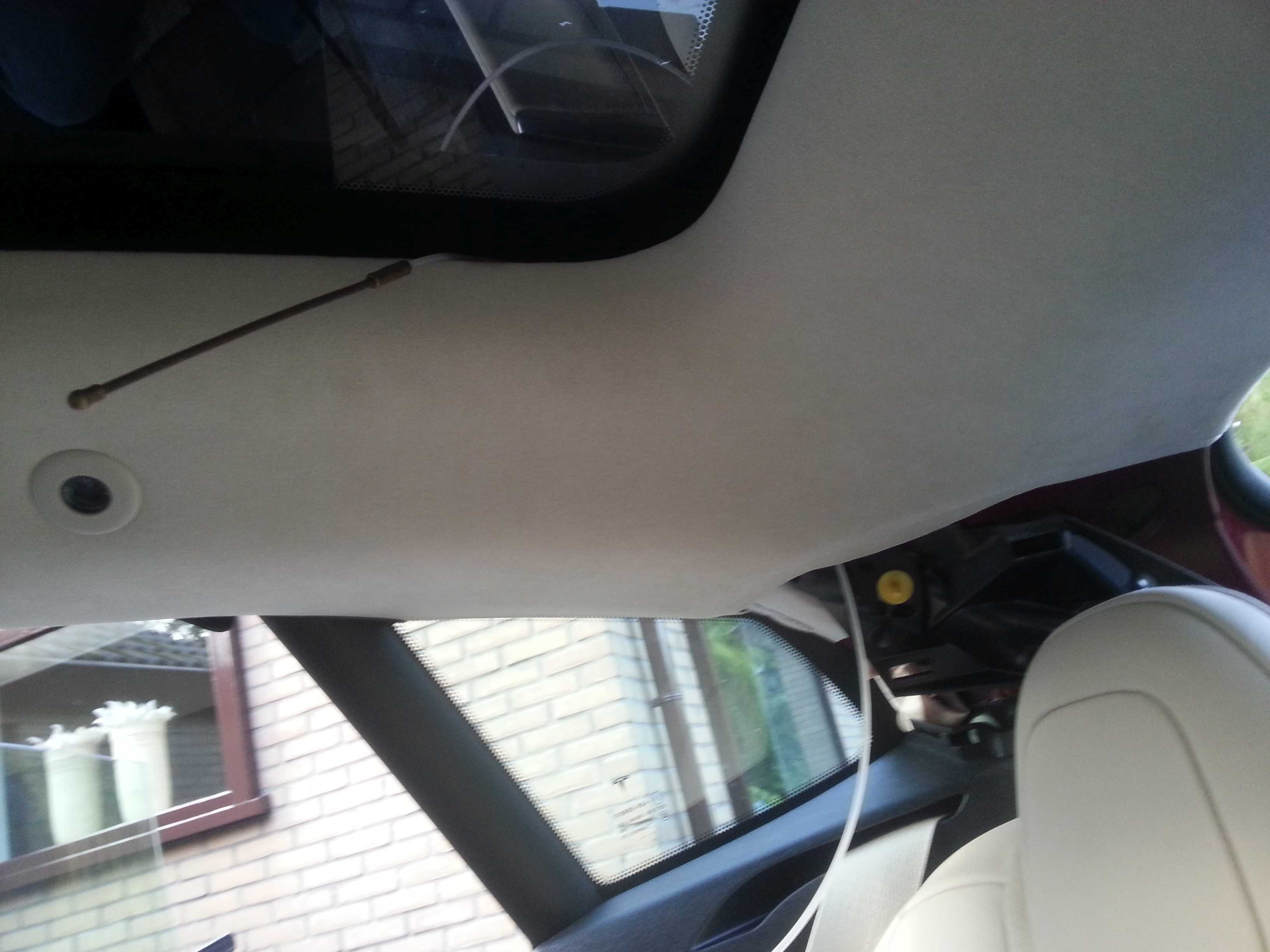
For this and many next steps I used a couple of tools. One is a nylon wire with a sping at the front end. This thing is regularly used to install wiring in the house (pull wires thru a tube). The second is an old car radio antenna (but any piece of somewhat flexible wire/metal would do the trick). I used both to get the wires from one side of a hurdle to another by pushing the tool thru from the opposite side, tape the wire to the tool and pull it back to feed the wire thru.
You can also use this to get the wires from the mic opening to the pano roof side.
Using your fingers put the cables under the roof lining toward the front right corner of the pano roof.
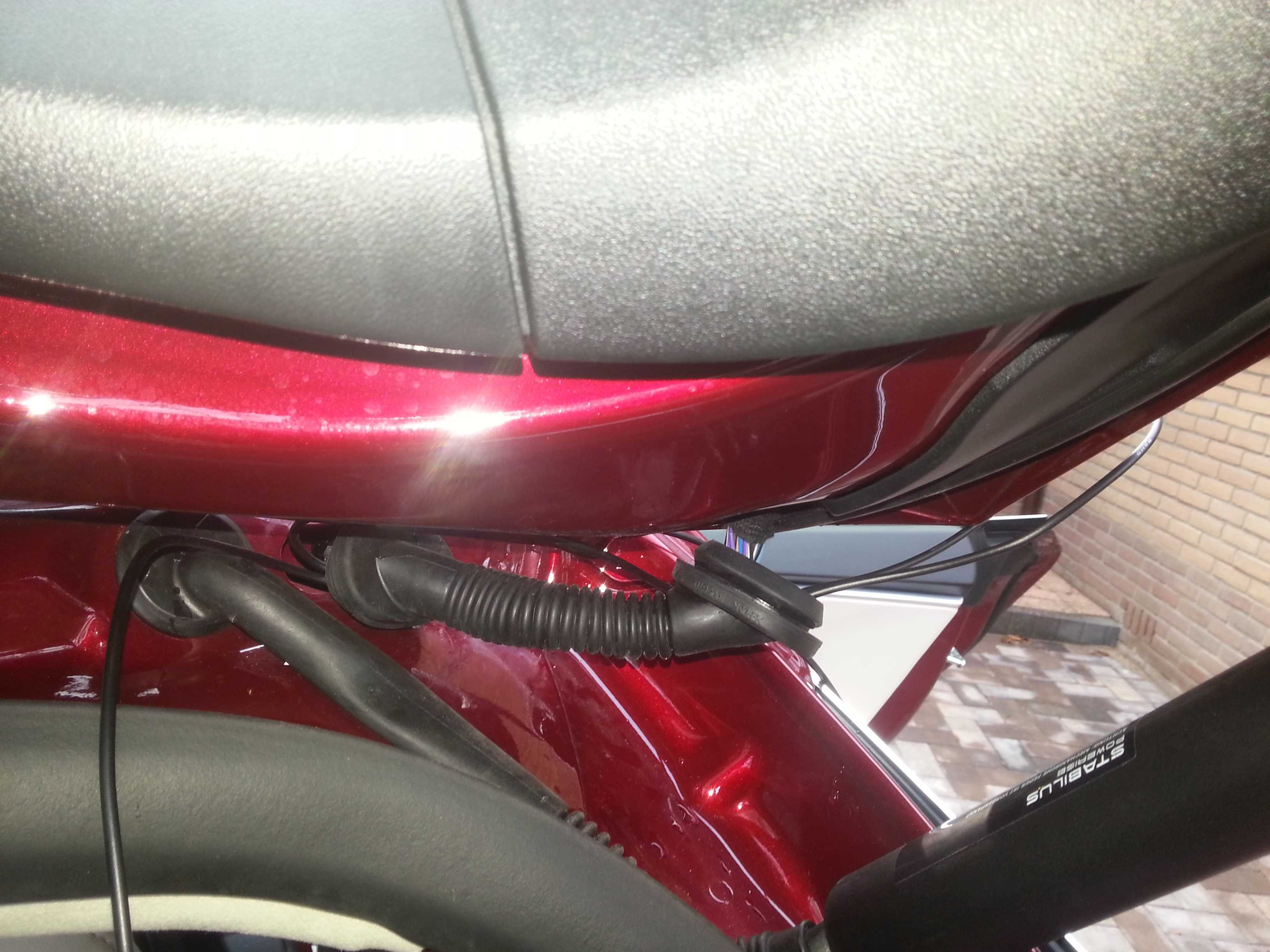
Now remove the rubber door sealing along the roof lining (if you had not done so yet in one of the earlier steps).
Loosen the A-style cover by prising out the plastic cover with �airbag� on it and removing the bolt/screw. Pull the cover loose. But you do not need to remove it.
Open the pano roof for easier access
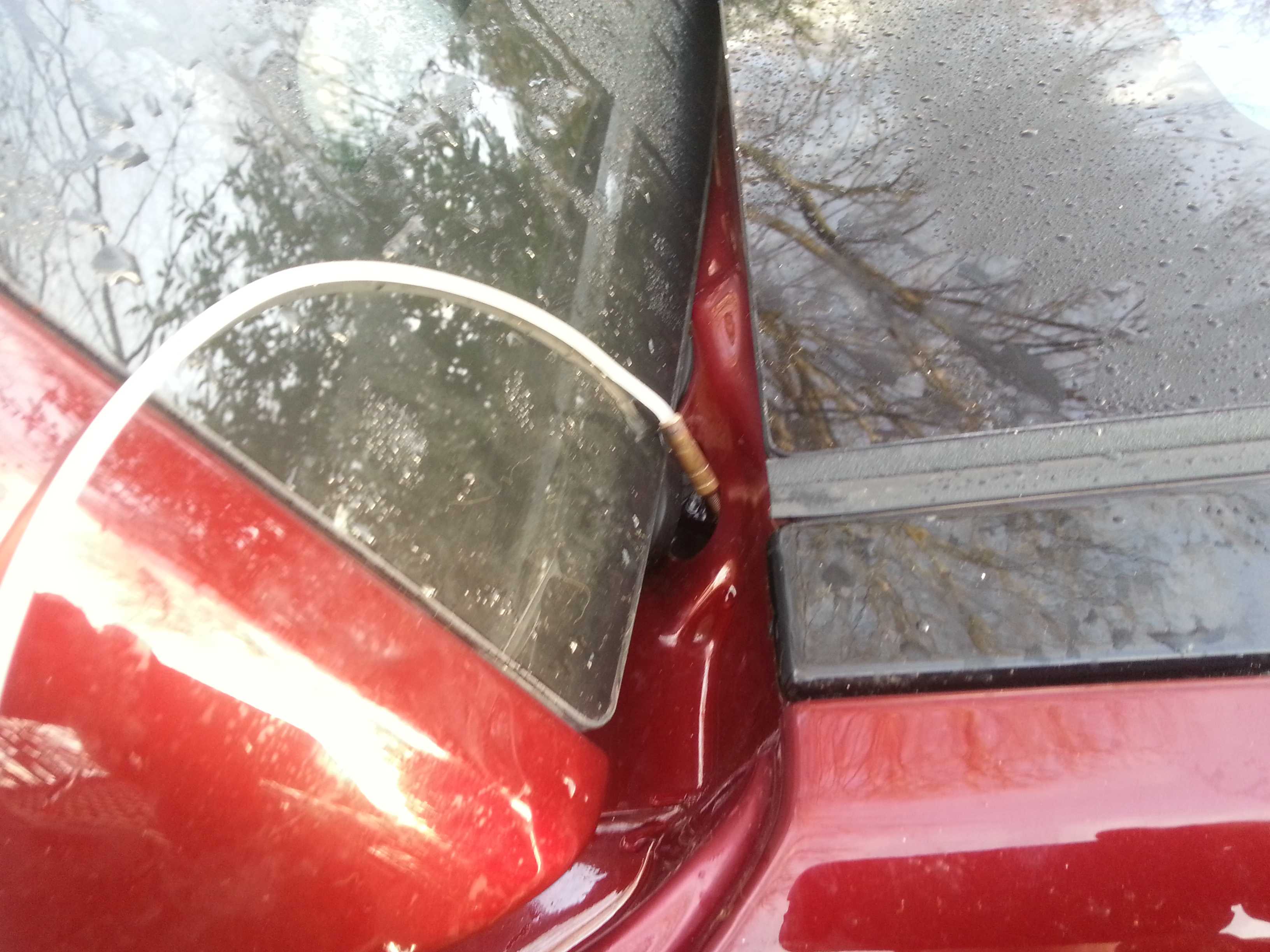
Slightly pull down the roof lining on the door side and push one of the tools thru in such a way that it comes out on the pano roof side. Tape the power cable to the tool and pull it thru. (note: ONLY the power cable as the cable for the back camera will be routed to the back of the car).
While doing this be carefull with the curtain airbags you will find along the side of the roof. Go between the roof and the airbag so that in any case the cable wil be at the non-expanding side of the airbag. (the end result should be that the power cable is not crossing the airbag at all)
With the power cable out on the side of the car, it should be easy to route it towards the A-style. Do this in such a way that when routed the cable completely stays inside of the curtain airbags. (sorry no pictures)
At the A-style you can join the exising cabling to bring the cable down towards the dash, ultimately bringing it to the side of the dash where the terminal was created.
Cut the power cable to length, connect/solder some connectors to the wires and connect them to the power supply connectors. Tie the wires up behind the frame of the dash (see earlier picture).
Along the way, I did many sanity checks using a multimeter to verify the connections/power supply. (recommended).
At this point you can do a first functional test by plugging the power cable into the front cam. If the power supply is OK some lights will come on and the BlackVue will start to talk.
You can now refit all the panels. The rubber door sealing is a bitch. I still have not figured out how to get it 100% back in place.
I also had some trouble fitting the doorstep cover back in. Make sure it�s far front end slides beside the panel at the end of the foot well (not against it).
Now you are ready for the second stage: routing the back camera cable. (I took a break before doing this. I even waited for the following year�)
Routing rear camera cable
Following the right side of the pano roof, fit the cable between the roof lining and the roof.
At the cross bar use a tool to pull the cable thru to the other side
Again follow the side of the pano roof
In the trunk, remove the parcel shelf mount panel. Undo the screw from the underside. Then pull it towards you. It is fitted with 4 clips.
(note that the wire is from the LED strip I installed to improve trunk lightning; so don't panic if you find out that you don't have that wire on this piece)
Subsequently remove the C-style cover. Just carefully pull it out. 3 clips on this piece.
Using the tool again feed the cable thru from the corner of the pano roof to the c-style
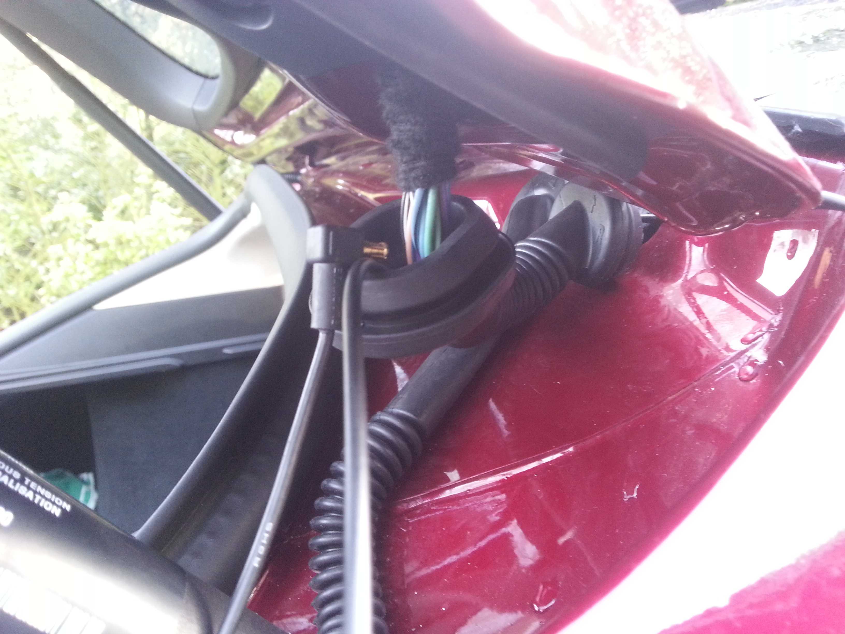
Open the trunk. Pull the rubber wire protector/seal (from car to trunk door) out on both sides
Feed the tool thru from the outside to the inside (c-style). This involves 2 holes that are not fully opposite to each other. You might have to guide the tool with your fingers from the inside.
Pull the cable thru.
You now get to the most challenging part of routing this cable: feeding it thru the rubber seal. As the connector for the camera is hooked, rather than straight (as it was in earlier sold versions), it is a rather large object to get thru. But... it can be done!
First feed the tool thru from the tail gate end. Tape the wire to the tool (some distance from the connector end of the cable). Really tape it well. Taping the connector to the tool would make the object too large to pull it thru and the tape is likely not to hold.
Now pull the tool back thru the seal. Do not just pull. Rather combine the pulling with some �massage� on the seal. Pull and push the seal to help the tool/wire get thru. (this is 'massage practice' for the next step).
Tape the connector to protect it and to make it somewhat smoother object (not to get stuck or cut into the seal or other wires). Then �pull� the cable and connector thru the seal. Even more than the previous step be careful with the pulling. In the first stage you will have to push it more (from connector side) to help it get passed the tighter/stiffer car end of the seal. In the second stage you will have to massage it thru the flexible part of the seal. You can actually pull/stretch the seal over the connector in small steps. In the third and final stage you have to pull/push it thru the tighter tail gate end. In any case never pull too hard on the wire because the last thing you want is to break the wiring inside the cable.
Done!
The time indication on the pictures files shows that I spend about half an hour on this step�
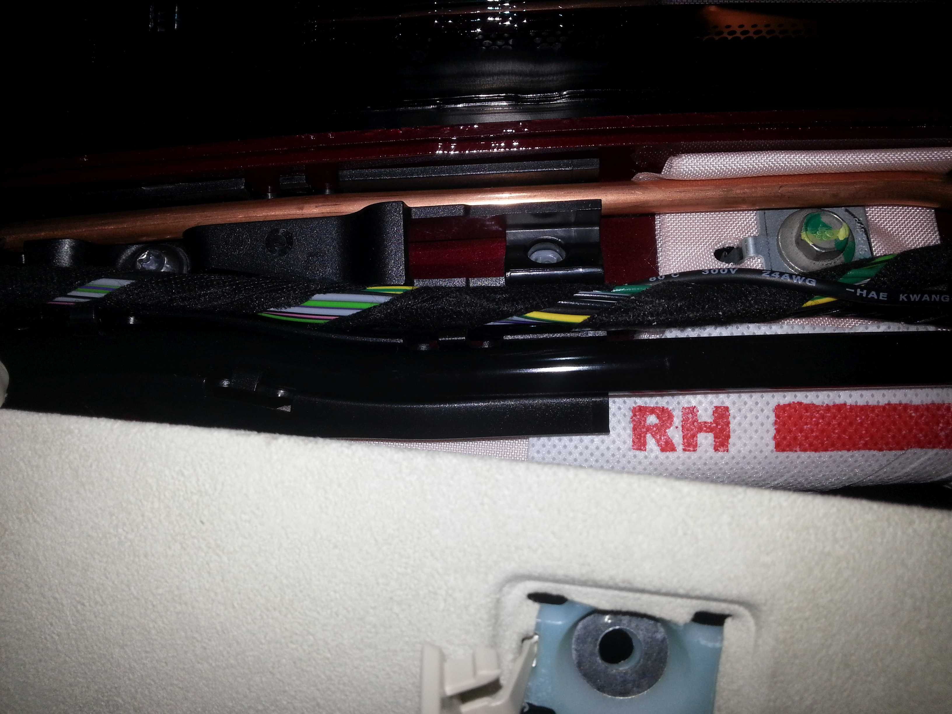
Now remove the top window edge cover (comes off very easily):
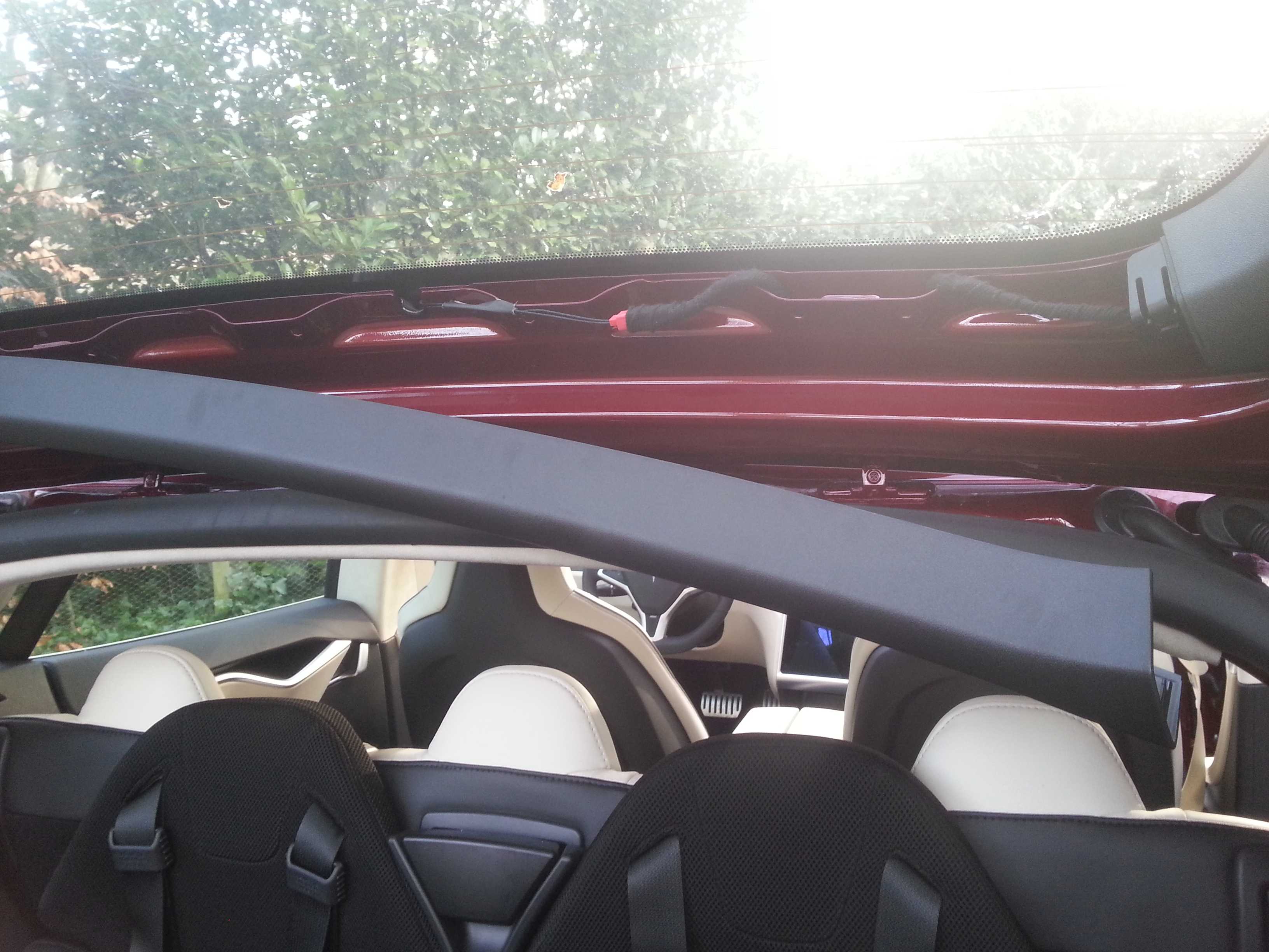
And the right side window edge cover (3 clips, if they stay in, they are a pain to remove, you are likely to have to replace them; you can see one blue clip, that stayed in, in the picture).
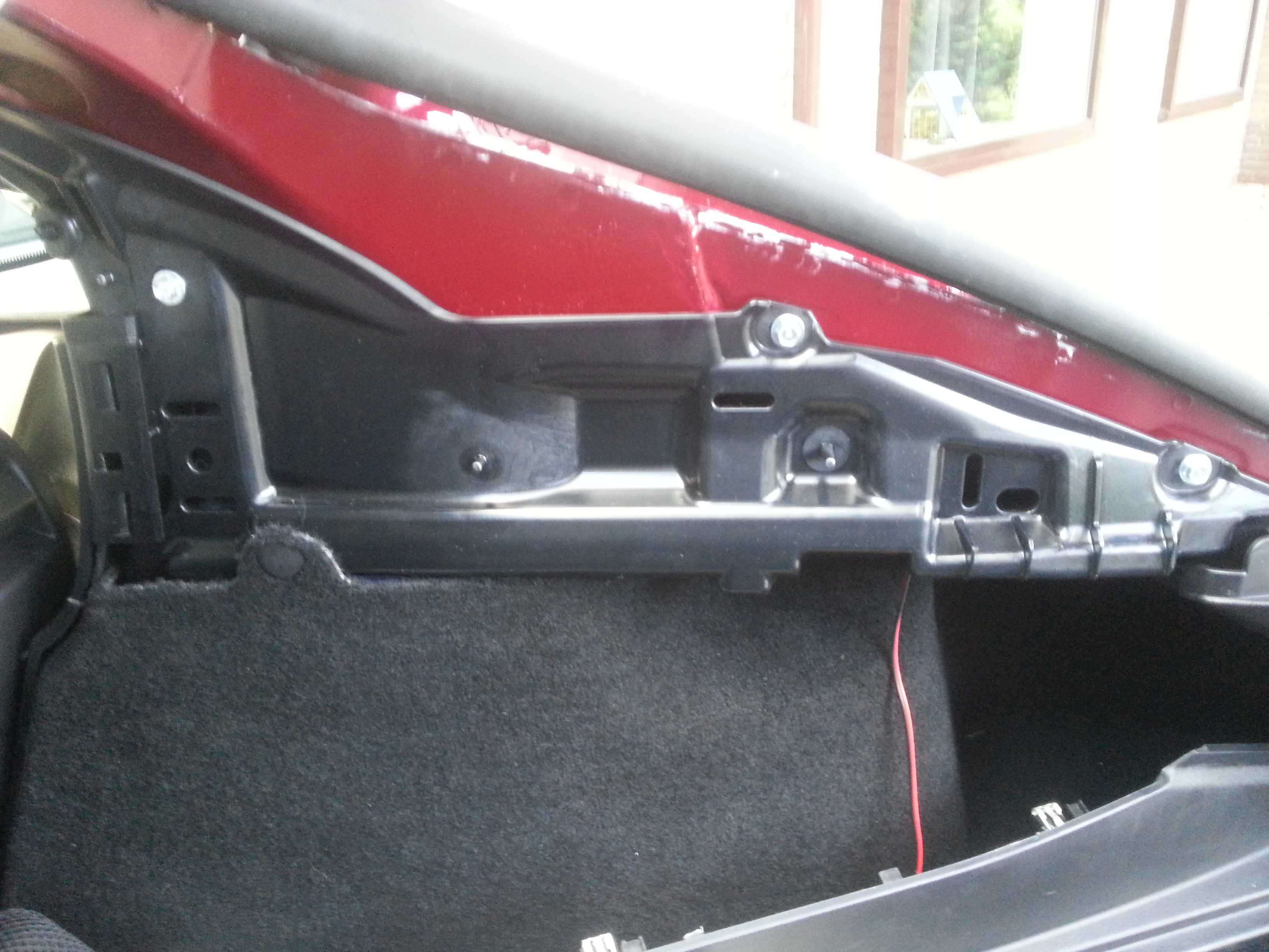
At this point I discovered that the original wire beam goes all the way to the bottom end of the tail gate. The wiring for the brake light comes back up again from there.
Although the cable is long enough to do the same with the cam cable, I did not fancy taking all these panels off. (not sure how they are fixed and did not want to break any more clips, etc.).
I tried a shortcut thru one of the holes used for the panel clips (see above picture). But this hole is too small to get the connector thru.
Subsequently I figured I could create my own shortcut here. So I drilled a hole to get the cable and connector thru. (I understand some might feel uncomfy drilling a hole in their 100k toy... :redface
I taped the inside of the hole and the cable at that spot to prevent any cutting from the edge of the hole.
From here the rest is straight forward. Route the cable along the brake light wire to the center of the window. Then fit back all panels, seals, rubbers, etc.
With all cables in place the last step is to mount the camera�s. As this seemed trivial (BlackVue manual for reference if needed) I did not even make pictures of it.
Tips:
With the panel still off you can easily mark the center of the tail gate window (center feature in the metal frame; see above picture). Mark the center on the window before putting the cover panel back.
If you mount the rear cam close to the top of the window, it is not visible in the rear mirror.
HAVE FUN DOING IT YOURSELF!
will shoot some pictures of the end result and add to this DIY later�
Jan 11, 2014
gelden Great description! Thanks.�
Jan 11, 2014
S-19910 +1.
But I'm not so keen in taking my car apart... I'm sure I will break some clips.�
Jan 11, 2014
JPP Outstanding--great guide and good photos. Very timely as I ordered the same dual camera dash cam yesterday. I fortunately have continuous 12V power in the microphone compartment (older build) so no need for me to find 12V in the glove box.
Wish you had the courage to remove the bottom trim panel inside the trunk lid to see if you could have routed the cable all the way down without having to drill a hole. Note that to protect the sharp edges of the hole you could have gotten a rubber grommet.
Many thanks!�
Jan 11, 2014
EarlyAdopter Has anyone discovered a continuous 12V source in the rear of the car? Maybe a line to a speaker amp?�
Jan 12, 2014
LastNLSig
100% sure you can remove the bottom trim panel and route the cabe up and down. Down via the hollow space inside the metal frame (like the main cable beam), up on the 'outside' covered by the trim panel.
But there is nothing 'wrong' or difficult in drilling a hole...
Rubber gromet would have been ideal, but you know how it works: almost there, last hurdle tackled, eager to finish the job. (so no time/motivation to go shopping again)
By the way, I forgot to mention that there still is a lot of excess cable (more than enough to go up and own the trunk lid). I kept this inside the car and tied it up under the roof lining near the C-style.�
Jan 12, 2014
widodh Looks great. I'm still thinking about buying a dashcam. I've never been into an accident, but what always scares me is people merging onto the highway with 50km/h while I'm doing 120km/h.
Anyway, so there is no continues 12v power supply in the rear of the car? For now I've only been thinking about a front mounted dashcam, that seems to be the easiest one.�
Jan 12, 2014
LastNLSig What do you need the 12V power suppy in the rear for?
The BlackVue cable for the rear is signal cable with phantom power supply.
Or would you like to install a stand alone cam in the back?�
Jan 12, 2014
widodh Aha, I didn't know that about the cable.
But a rear power supply would save you routing the whole cable, simply install a stand alone cam.
I probably have to learn more about dashcams") �
�
Jan 12, 2014
ojee99 Hi Widoh,
that cable is also nessecary for controlling the rear cam and storing data on the memory card in the front cam, so you DO need that cable from front to end. This makes both cams to be controllable and have them store images all in one place, easy-peasy!�
Jan 12, 2014
EarlyAdopter I've already installed a dashcam up front and now am thinking about putting another one in back. Just wanted to know if anyone had found a continuous 12V source back there yet.�
Jan 12, 2014
JPP Guess it depends how hard it will be to remove the side trim panel (the one you had trouble with and breaking the blue clips), as well as the bottom one with the speaker grilles. FWIW, I went to my local hardware store today and bought a few grommets and also some plastic spackle/putty knives to use as pry/push tools to route the cable, plus some heat shrink tubing. Expect to tackle this next week when I have some free time. I will try to post any new/better photos and info (but doubt I can do better than you--thanks again).�
Jan 13, 2014
LastNLSig The surprising thing is that it came off without a lot of force. Also the blue clips did not really break. They managed to slip out on the panel side and thus stay in the hole in the metal frame. Once you try to remove them from there it seems impossible not to demage them.
This type of clips is widely used in car manufacturing. Encountered similar behaviour with my VW's (clip staying in the hole). However they were always easy to remove afterwards.
The blue clips are made of a rather hard, brittle type of plastic. So it might be wise to score a few next time around at a service center.
It is also likely that clips from other brandmarks will do the job as alternative (have not tested that yet).
The lower panel did feel like it needed a lot of force to remove (after a few clips at the higher end did release), that's why I decided to leave it alone.�
Jan 13, 2014
JPP Makes sense--yes, maybe I get a few blue clips in advance if I dare to pull the other panels. Odd, as the panel at the top edge of the window seems to pull out easily and has these clips.
News later....�
Jan 15, 2014
Laumb Very nice! Did the same thing on sunday - just havent finished the last part on the rear and havent connected the power.
Was the glovebox light plastic piece easy to pull? Grab and Rip?
Picture of the side panel tabs:
 �
�
Jan 15, 2014
pete8314 When I was installing my 9500ci, I spent a long time trying to pry off the glovebox panel around the light, since that was a potential location for the GPS antenna, and a potential live tap. Anyway, I never did manage to get it off, so some more suggestions around that would be helpful. I also agree the plastic around the rear view mirror mount is horrible, I may have broken one of my tabs before thinking better of it and leaving it in place. All the big panels pop off really easy though, but make sure you use a proper pry tool, makes things a lot less scary.�
Jan 17, 2014
LastNLSig I don't remember it as being hard to pull. As long as you pull on the larger piece (not the light itself).
Just pull the front end down.�
Jan 20, 2014
JPP Just finished my own install of the same Blackvue dual camera dash cam that LastNLSig has so clearly portrayed above. I thought I would share some of my own observations after the install (warning--long).
First, many, many thanks to LastNLSig for his detailed and excellent instructions and photos. I would not have tackled this on my own without this wealth of information.
Second, be sure to allow lots of time to do the install. You need to take it slow and steady, anticipate problems and delays, be sure to check and recheck your cables, connections, power wiring, etc. It took me 3 hours of work by myself.
I had the benefit of an older Model S build which has the small connector above the speaker grille in the headliner with continuous 12V power, so I did not need to do the glove box access for power.
Knowing some of the issues noted by the OP, in addition to the array of tools and supplies I have around (soldering iron, drills, tape, coat hangers, tape, shrink tubing, and the like), I went out and bought some rubber grommets to be able to protect the hole I assumed I would have to drill to run the rear camera cable. Also, I bought a set of plastic putty/spackle knives to be used as spudgers/pry tools to get under the headliner and other gaskets and trim when pulling cables.
Before I began, I connected up everything and plugged it into the 12V outlet. The camera does an initial SD card format, then boots up. I made sure that everything worked, including the WiFi and my iPhone app. Next, I powered down the camera, popped out the micro SD card, and did a firmware update (latest firmware released in the last few days). I also updated my iPhone Blackvue app (also just released). I popped the SD card back into the camera, booted it back up, waited for the firmware update to finish, and rechecked everything yet again.
I started in the rear with the tough job of running the rear camera cable. I pulled the right rear parcel shelf trim-note that the single screw on the underside is a Torx and not a Philips. With the screw out, this panel pulled out easily, followed by the passenger side C pillar trim. Note that when reinstalling these trim pieces, they tuck under the rubber gaskets, so be sure to tuck the proper edge of these trim pieces under the gaskets before trying to tap/snap these back into place.
I then pulled/removed the trim along the top edge of the rear hatch/trunk window, where the cable was to be run and the camera installed.
I then addressed the right hand trim on the window frame, the one with the 3 blue clips that seem to break (as noted by the OP). What I discovered is that these clips slide into slots on the trim piece, and, as you pull outwards to remove the trim from the clips, you need to simultaneously pull/slide the piece down towards the bottom of the window (towards the trim piece with the speaker grilles). With luck, the blue clips will actually stay in the metal frame/body work, and the trim piece will come out without breaking the clips. I then used a small screwdriver to pry out the 3 clips which I could then slide back into the slots on the trim piece, so that I could snap the piece back into place when I was done running the cable.
I then pulled the 2 ends of the rubber sleeve/boot that contained the cables out of their holes in the body work (as in the OP's info/photos).
To fish the cable, I chose to use (where possible) a long strong plastic zip tie/tie wrap. This is flexible and non-conductive, and being plastic and not metal, I could worry less about scratching or breaking something or doing other hidden or not so hidden damage. I initially fished the rear camera cable from the C pillar back to the opening for the cable boot. I then tried to use a zip tie to push through the boot, but it had too much drag. I took a length of wire coat hanger, put a small closed tight loop at one end, then pushed it through the boot/sleeve from the rear hatch side to the body/jamb side. I initially toyed with the idea of trying to crimp/tape my fish wire directly to the connector and pull directly, but dismissed it due to my concern about damaging the rear camera connector (the right angle connectors are great for attaching to the camera, but miserable to fish). I used the OP's technique of hooking onto the cable itself, and thus pulling 2 thicknesses of the cable through the sleeve/boot. I then used the technique the OP detailed above, pushing, pulling (very gently), massaging, coaxing, praying, resting, rubbing my hands, etc, and after about 30 minutes was able to get the right angle connector through the sleeve/boot. This is a slow painful slog, and I was continually worried about damaging the cable.
Even though I had the right hand trim piece on the hatch fully off, I still could not get to the bottom edge where the cables apparently exited for the stop/turn lights. Thus, I chose to drill the hole in the frame exactly as the OP did (thanks again for the photos). I used a zip tie to fish the connector and cable through, slid an appropriate rubber grommet over the cable, then set the grommet into the hole to protect the cable from the raw metal edge of the drilled hole. I made sure I had enough cable to reach the camera, then took a break.
At this point I decided to again test everything, especially to be sure I did not damage the cable. When I powered up the system, the rear camera was not found/recognized. I rechecked every connection, rebooted the system, all to no avail. The rear power light was on, but it was not working. Panic--did I damage the cable? As a last resort, I held down the button on the front camera for 10 seconds to start an SD card reformat. This fixed the problem, and all was working OK.
Next, I went up to the front, and ran the rear camera cable from the rear view mirror exactly as noted by the OP, using the plastic putty knives to make room under the headliner and trim, and tucked in the cable.
I went back to the rear, and rechecked cable length. I then pulled back excess cable into the C pillar (exactly as the OP did). I then replaced the 2 ends of the rubber cable sleeve/boot and the right hand trim (the one with the blue clips). I loosely placed the top window trim, and installed the rear camera, being careful to have it pointing the right way (up/down). Note that the cable connector will point to the driver's side of the car, not the passenger side. I adjusted the cable, and snapped the window trim into place.
I rechecked the whole system again. I noted that I could see the fine lines of the rear window defroster on the read camera images, even after trying to adjust the position of the camera. I could find no optimal position, and think that it has to do with the steep slope of the rear hatchback window and the arrangement of the resistive wires. It is not that noticeable, but for me, unavoidable.
I then reinstalled the C pillar trim and the rear parcel shelf trim.
Now to address the 12V power. My Blackvue camera came with a power cable that had both a fuse in the barrel of the cigarette lighter plug (typical), plus a 2nd in-line fuse holder about a foot from the lighter plug. Maybe they knew that many folks would hard wire and cut off the cigarette lighter plug. It was nice to not have to buy a new fuse holder. I initially wanted to keep the whole assembly intact, with no splices, which would have required me to fish the right angle small power plug from the microphone grille opening to the front edge of the headliner at the windshield. I tried, but there was not enough room to pull the connector through. So I chose to cut the cable, and then it was easy to fish the cable back from the headliner into the opening for the microphone. I just soldered the red/black wires back together (reconnecting the in-line fuse holder) and protected them with heat shrink tubing and black tape.
Next I installed the front camera--straightforward. I then adjusted cable lengths, and tucked the cable under the black rear view mirror trim plate (which I did NOT remove). Just used the plastic pry tools to make room to tuck the cable.
Back to the power cable in the microphone space. I used the soldering iron to tin the bare ends of the stranded red and black wires. I then popped open the 3 pin connector that was found in my Model S build, and rechecked the voltage/polarity. As others have noted, red is hot and black is ground. I laid the red wire from the power cable on top of the red wire in the open connector, and the black on the black. I snapped the connector closed and pulled on the leads to be sure that they were tight and secure. This technique has been noted elsewhere (thanks to the pioneers...). I then shoved the small in line fuse holder into the space above the headliner, rolled up the excess power cable and tucked it away, and popped the microphone grille back into place. Some owners have actually bought the appropriate multi-pin plug to fit into the empty connector, but I wanted to save the connector and leave it empty in case Tesla did actually come out with some accessory (lighted visor mirrors?) that needed this connector. Probably unnecessary, as later Model S builds apparently do not have always on 12V power up there.
Finally, I connected the rear camera cable to the front camera, then connected the power cable. The system booted up. I turned WiFi on, and using my iPhone and the Blackvue app, used the live images to adjust the cameras to optimize the field of view. I also used the iPhone app to set up the camera (time zone, indicator lights, event timing, etc).
Overall, IMHO this is not a job for an amateur hobbyist. I have a great appreciation for the expertise and skill of auto customizers, aftermarket audio installers, etc. They probably have better tools and tricks and the experience to make it look easy. That said, it is doable with the right tools, dexterity, and patience.
YMMV.�
Jan 20, 2014
LastNLSig Well done JPP! Isn't it nice to get to know your car a bit better?
The next one doing the install will again have an easier job.�
Jan 21, 2014
JPP ...trying to pay it forward....�
Jan 24, 2014
JPP Update...camera is working fine, with a few minor glitches.
GPS-probably due to the TM coated windshield, the GPS reception is spotty in the Blackvue (the blue GPS light does not sen to stay on all of the time).
Time/time zone--there is a known bug where the camera does not display the correct time even if the proper time zone is selected. Not sure if this relates to the GPS issue or not. Waiting for any additional info from the DashCam forums/blogs or Pittasoft.
RF interference--this has been commented upon on the DashCam forums, but apparently the long cable from the rear camera to the front camera is not well shielded, and gives off RF interference. This has been reported to cause problems with radio interference, with hum and noise. FWIW, I think that my already marginal AM-FM reception is in fact being impacted, so I have ordered some snap on ferrite cores to install:
Amazon.com: Gino UF35B 5mm Inner Diameter Black Core Ferrite Cable Clip 10 Pcs: Car Electronics
I will see if this helps. Note that many good quality cables (USB, power, data) come with integrated 'preinstalled' ferrite cores for this reason.�
Jan 24, 2014
pete8314 I'm sorry - quick OT question...on my Passport 9500ci install, I have an issue where if I honk the horn, my laser alert goes off. I'm guessing the feeds from the shifters run near the horn wire, so would putting cores at each of of the laser wires fix it, maybe? I really don't want to pull my entire frunk and dash apart to reroute the wire, but if something like this could fix it, that wouldn't be so bad....�
Jan 24, 2014
nkohlimd Seems like they have released a new cable to reduce interference
New Coaxial cable for Blackvue DR550GW-2CH | Blackvue UK News Blog�
Jan 25, 2014
JPP ...like I want to struggle to deinstall my existing cable and reinstall the new one....
I did get the ferrite cores and have installed them near the rear camera (behind the window trim) and in the right hand A-pillar. Seems to have helped.
BTW, time/clock now set properly--probably needed a good GPS link. The GPS is still intermittent (get the blue light off and on).�
Jan 31, 2014
JPP FWIW, I got in contact with the seller of my Blackvue (through Amazon). He got a few of the new better shielded rear camera cables air-shipped to him and is sending me one. I will look at it to see how it measures up and if it is worth the effort to deinstall the old one and install the new one. I do have a couple of ferrite cores on the cable now, 1 at the rear near the camera (looped with 1 full turn of cable through the center), and a second in the A pillar (probably redundant).�
Jan 31, 2014
nkohlimd JPP
let me know how it goes. My unit gets delivered Monday and will wait on install of the rear camera to get up your input on whether the new cable makes a difference. Best of luck. Thanks.�
Feb 1, 2014
dratifk I can't get my time and date to set properly. Any tips. I tried erasing all the files in the record folder and rebooted.�
Feb 1, 2014
JPP Time and date rely on a good solid GPS lock for a period of time (...hours to days). Are you parked inside a garage or out and about? Do you see the blue GPS light on the unit when driving?
Do try to do a full SD card reformat (in the camera or on the desktop).
- - - Updated - - -
I might not do the cable swap anytime soon--given how much work it was to fish the cable through the rear rubber boot/sleeve. If I have the energy, guess I could just disconnect the installed old cable and use the new cable tossed over the seats to see if there is any improvement. As of now I have little-to-no noticeable interference with the ferrite cores.�
Feb 2, 2014
ntt6 Hi, I had a professional install the 550 front/rear a few days ago following LastNLSig's step-by-step (thanks!). Ever since my car refuses to go into sleep mode (as I can see through the REST API and the speed of connection with the Tesla App). Do any of you have the same problem or any idea how to fix this?�
Feb 4, 2014
JPP ntt6--not sure why car won't sleep after install of Blackvue. I would not think that the 12V draw should affect the MCU. FWIW, my S sleeps fine (...maybe too soundly-slow to wake up).
Follow-up---got the new improved cable from my US/Amazon seller. Looks thicker but otherwise unremarkable (no built in ferrite core, no lumps or bumps, same right angled connectors). No time now to do an A-B comparison.�
Mar 4, 2014
ABVA I have an INAVI FXD900. In the process of installing the camera I think I damaged the Power supply cable. Does anybody know where can I get a replacement cable within USA. Any help is sincerely appreciated.�
Jun 5, 2014
Akikiki Hey, LastNLSig,
Reference your comment about power:
Cut the power cable to length, connect/solder some connectors to the wires and connect them to the power supply connectors. Tie the wires up behind the frame of the dash (see earlier picture).
"Along the way, I did many sanity checks using a multimeter to verify the connections/power supply. (recommended).
At this point you can do a first functional test by plugging the power cable into the front cam. If the power supply is OK some lights will come on and the BlackVue will start to talk."
I wish for you to confirm what I found. Was it your experience after testing for 12v positive that it was the inside of the 12volt connector connecting to the cam? Am I correct that the inside of the connector where you too connected to 12volt on the car/glove box power?
thanks.�
Jun 5, 2014
AnOutsider I'm curious, those who tapped power for these to run continuously, do you noticed less range? More vampire draw? I'd imagine it should be negligible, but just curious.�
Jun 5, 2014
Johan Totally negligable. I don't think it would effect vampire but in theory range for the first few minutes of driving (putting energy lost back in 12V battery). I left my DR500 on for one week (WiFi off) and the 12V was at 13.2V when i returned (checked before starting the car, but with doors opened).�
Jun 5, 2014
AnOutsider Ah duh, it draws from 12V and not high power pack. I may consider this. We're going on a road trip and it would be cool to have this.�
Jun 6, 2014
HankLloydRight How do you check the 12v battery voltage.. Pop off the nosecone and use a voltmeter?�
Jun 10, 2014
Akikiki Power Source in Speaker Grill of newer Model S
Just finished the install of the Blackvue 550 front dash cam following most of LastNLSig moves. I found something that made my install easier.
I found a constant power source in the speaker grill. My S was built after 1 Aug 13 and that's supposed to make it different in many ways. But I found power up there anyway. I had to dig around a little. It was not connected to anything. There's several wire/cables pushed up against the headliner towards the mirror; this one was in that group.
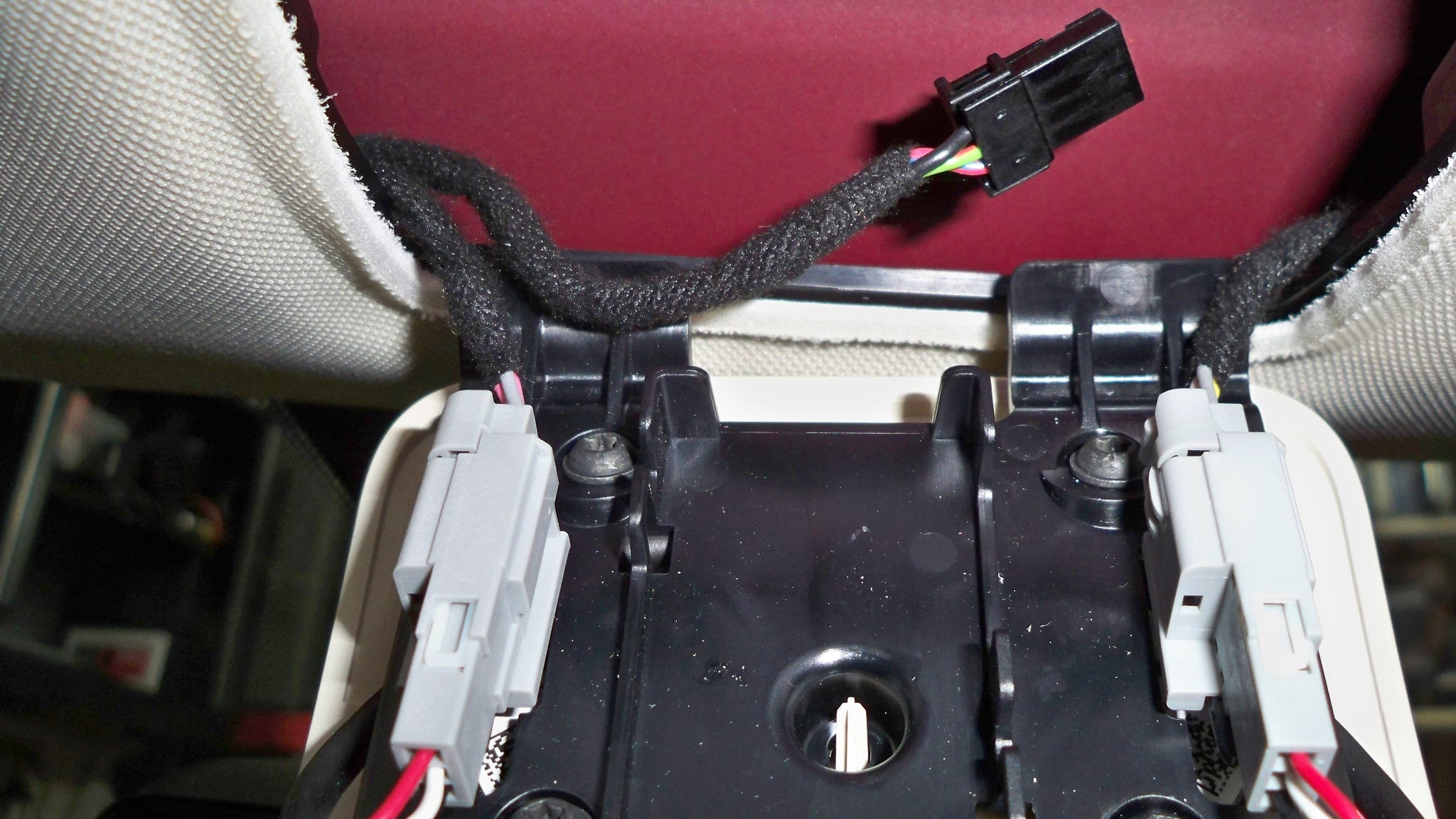
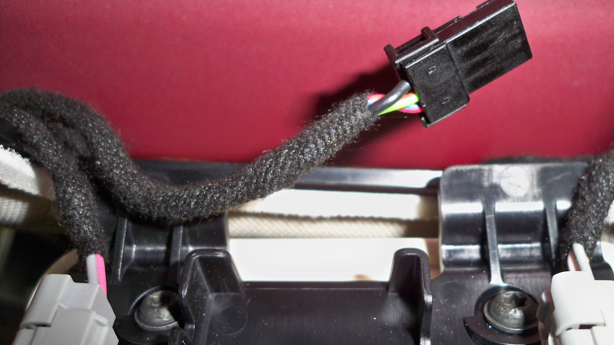
Here's a picture of the connector. There are three leads coming into this connector. Black is ground, and the green-ish (middle) and blue/red (outside) are both constant hot. Even when the car has shutdown/gone to sleep.
Also on Amazon I found a 1.3mm x 3.5mm x 11.2mm plug (pigtail) with 6 feet of cord for the power from Parts Express. Saved me cutting my Blackvue power cable just to get that plug.
http://www.amazon.com/Parts-Express-1-3mm-3-5mm-11-2mm/dp/B000LFRT8K/ref=sr_1_2?ie=UTF8&qid=1402457345&sr=8-2&keywords=Parts+Express+1.3mm+x+3.5mm+x+11.2mm+Plug+with+6+feet+Cord�
Jun 11, 2014
JPP I'm surprised that there is still a 12v supply in the headliner above the microphone grille at VIN 20800--thought that was eliminated around VIN 10000 or so.
BTW, did you leave a fuse in line with your Blackvue? The original cable has a fused cigarette lighter plug and also an in-line fuse holder. Your substitute cable has neither. FWIW, I cut off the cigarette lighter plug but kept/use the in-line fuse when I connected to the 12V.�
Jun 11, 2014
HankLloydRight Strange -- my VIN 15xxx does NOT have the headliner 12V harness.�
Jun 11, 2014
Akikiki JPP. Yes, I added a 5 amp fuse. I could not find anything smaller. Thanks for asking just as a reminder to me in case I had not.
Hank, I would poke around a little. I too thought it was not supposed to be there. I had heard some time ago it was missing. Surely made the front mount install easier.
I had contacted my seller for a newer cable to the rear. After hearing others having an interference problem. Getting the cable and end through that boot between the body and truck lid was quite the chore. I worked more than two hours on different methods. I removed the right side plastic trim panel on the lid in order to drill my exit hole there.�
Aug 21, 2014
LastNLSig manni786 clean up your PM inbox. It is full so I cannot reply to you.
To answer your questions:
I have the blackvue on 24/7 with a 64Gb sdcard (never checked but should be recording about 24hrs). Of course it draws energy from the battery, but this is minimal (compared to what you have available, and possibly you are plugged in overnight at home anyway). I don't know whether there is an option to program the on/off time of the blackvue.
WiFi I have only used to connect my SmartPhone. Press the button on the right side (where the connectors are) to switch WiFi on. Install the app on your phone and connect to the blackvue wifi network and it should run smoothly.
Never tried to catch the wifi with a desktop or laptop computer.�
Aug 21, 2014
Olle I installed a Blackvue 550 similarly to LastNLSigs excellent description and then connected to the constant power source above the microphone (early car).
My addition to the tips here: Put some vaseline in the rubber hose between roof and lift gate and the rear camera cable slid through like nothing :smile:
Now the car doesn't want to go into sleep mode though. Does anybody have any ideas about how to solve this?�
Aug 21, 2014
gelden I'm about to order a dashcam (this one: TEER H7000 HD 1080P 2.7 TFT 5.0MP CMOS Wide Angle Car DVR w/ HDMI / AV-OUT / GPS Track - Grey - Free Shipping - DealExtreme). I tried to open the central cover (in the middle of the headliner, near the reading lights) to see if i have the constant 12v there, but cannot figure out how to open this cover. Any hints?�
Aug 21, 2014
Olle on my car you start with pulling down the rear end of the microphone grille. But I have seen that they later changed the design and not sure the new one is fastened in the same way�
Aug 21, 2014
JPP Vaseline not recommended--there is an official cable lube that electricians use for this task (non-conductive etc). Probably would have made my pull of the coax cable easier....�
Aug 21, 2014
gelden I tried that. I can just look underneath (comes down about 5-10 mm) but it is still firmly held by something.�
Aug 21, 2014
Olle that's how mine was too, the outer cover bends down 10-20mm and then when you continue to pull down the upper plate with the two clips comes down from the retainer in the ceiling above.�
Aug 21, 2014
gelden Aha, so the black backing plate should come out?�
Aug 21, 2014
Olle yes. obviously spread the load over all your fingers so that the white plate doesnt crack..�
Sep 10, 2014
Chuck Lusin Looks like my rear camera when out. I had to replace my wife's BlackVue DR550GW-2CH because it would hang and stop recording. Anyone else having reliability issues with the BlackVue? �
�
Sep 10, 2014
JPP
Chuck--try the following:
Pull power--let sit for a couple of minutes and power up.
Disconnect and reconnect both ends of the coax to the rear camera, and look to see that the small pin is in the center. Be sure connections are tight. I assume no new bends/kinks in the cable.
Press and hold button on right side for 10+ seconds and reformat the SD card.
If none of these work, then maybe a bad cable or rear camera.
Me, no technical issues with my 550-2CH.�
Sep 10, 2014
Chuck Lusin Thanks JPP,
I only did a quick reboot at lunch, I'll check the wire to the trunk door to make sure it did not get crushed, also I have some spare BlackVue parts that I can swap it with.
The front camera is recording fine. The image was the live feed from the rear camera. I noticed that if you disconnect the rear camera and reconnect it, the app says "camera not found", until you restart the front one. It might just default to 500 single camera mode?
I'll let you guys know.�
Sep 14, 2014
Htuork I have the same exact problem with my Passport 9500ci, let me know if you find a solution.�
Sep 19, 2014
Chuck Lusin Well the rear camera did go bad, luckily I had a spare when I got a second 550 for my wife, when her front camera would just hang.
Now I have a box with a buggy front camera and a bad rear camera, which I'll see if I can warranty repair. Not much in the BackVue site about the warranty, only the request for help page.�
Oct 1, 2014
nhirsch I received the new Blackvue DR750LW and it apparently has a different 3-conductor power cord. Two conductors (yellow and red) are positive and one black negative. It's size looks similar to above except the barrel is split into a negative ground and the tip which is positive (as is the center also positive). I recommend you DO NOT use the one mentioned above for the DR750LW.
https://www.dropbox.com/s/uk1o1taqt9u60zq/DR750LWpwr.jpg?dl=0
https://www.dropbox.com/s/chpxd2fu0tys3vw/DR750LWpwr2.jpg?�
Oct 1, 2014
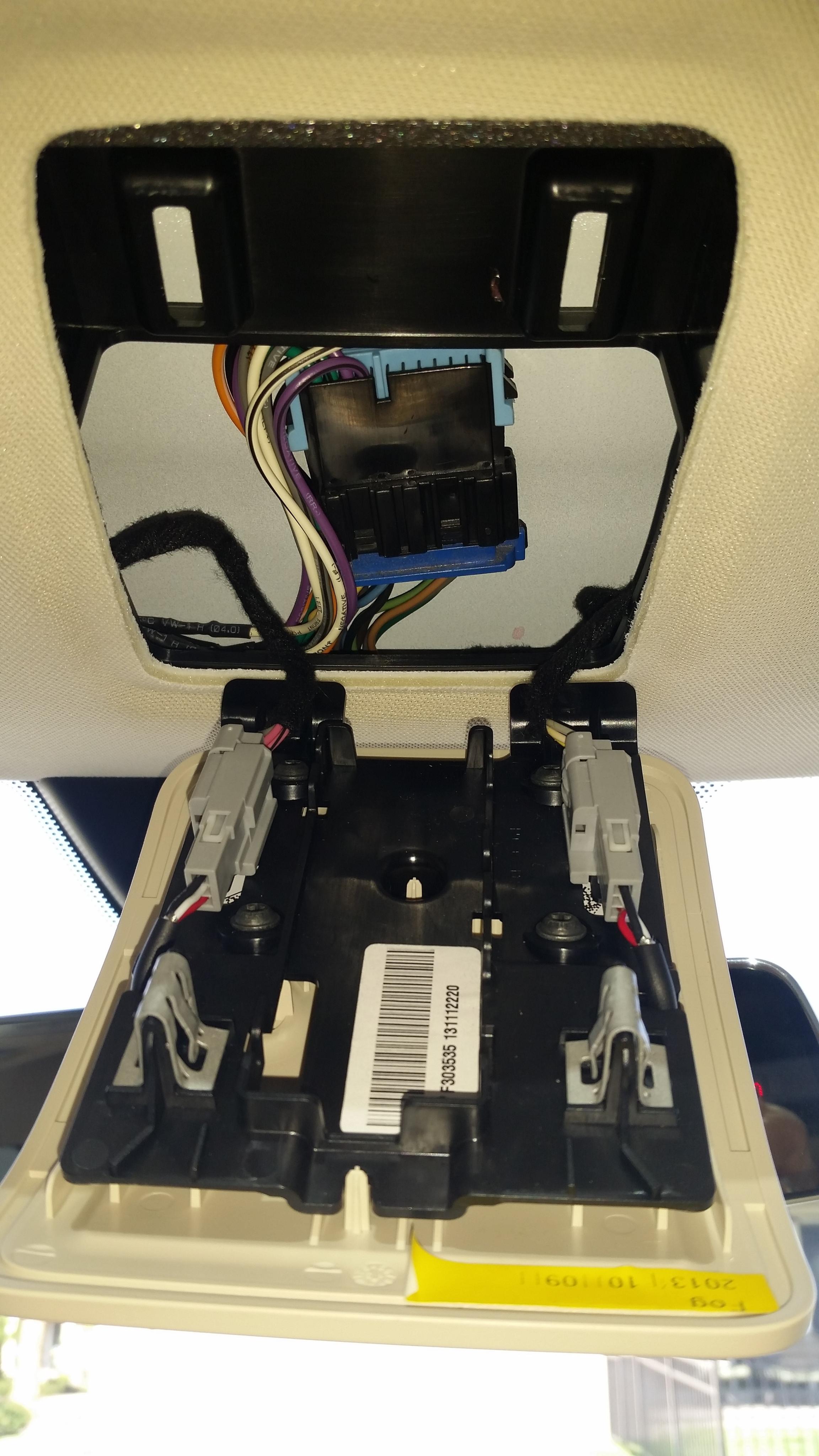
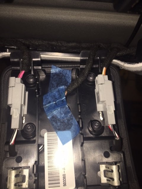
nhirsch Here's a good picture of what it looks like when open. Note the two clips that hold it in place.
Dropbox - microphonepanel.jpg�
Oct 2, 2014
nhirsch I found a hole thru the firewall which holds what appears to be a rubber drain hose. The hose is easily removed from inside. I'm thinking either put the 12V power cable from the #2 fuse box thru that hole next to the rubber hose or else drill another hole right next to it and put a grommet. Pictures are here:
Hole as seen from the Frunk with rubber stub removed from inside: https://www.dropbox.com/s/kcrbozznijqeo4t/outerdrainhosehole.jpg?dl=0
Hole as seen from inside car passenger footwell upper right: https://www.dropbox.com/s/ytvt6s2mj03qllh/innerdrainhosehole.jpg?dl=0
Passenger footwell area with carpet peeled back. Hole would be in direction of upper right hand corner of picture. https://www.dropbox.com/s/r8adcvd8dhiqmi6/passengerfootwell.jpg?dl=0
Plan would be to put power from Fuse Box #2, using add-a-fuse thru the hole shown above and routed along passenger door sill area shown below:
https://www.dropbox.com/s/844a8r48kmxgqdn/passdoorcablerouting.jpg?dl=0
and then inward under seat track and come up under passenger seat thru existing cutout in floor area as shown here:
https://www.dropbox.com/s/ys0o4l2unkq13rf/underseatcablesaccess.jpg?dl=0
there I would put an connector box as shown here on ebay:
http://www.ebay.com/itm/231035683042?_trksid=p2059210.m2749.l2649&ssPageName=STRK%3AMEBIDX%3AIT
I would remove the cable and replace it with the heavier power from the frunk and the ground from the passenger foot area. I would connect the cigarette plug of the Blackvue to one of cigarette receptacles. Alternatively I could unsolder the cigarette plug and plug it directly into the Fuse box #2 but this would not enable me to have a constant source of 12V under the passenger seat which might be beneficial such as charging cell phones when the car is off. I'm interested in anyone's thoughts. The ebay item i could double stick to the carpet and/or tie-wrap to the cylindrical seat motor to keep it tight. The car currently has a number of panels sitting in the trunk including the rear view mirror mount housing. Once I decide whether to drill a separate hole in the firewall or notch out a little more of the hole currently there -- enough for a grommet to protect the power cable, and also decide if I'm going to run a heavier power cable under the seat or just use the cable from Blackvue and forget the future options, I'll be ready to run the wires. The third option would be to run the Blackvue cable direct and while I'm at it, run the power cable thru there with the cigarette/usb adapter under the passenger seat additionally! Hopefully time won't be too long otherwise forget how things go back together�
Oct 3, 2014
nhirsch BTW, many, many thanks to LastNLSig and JPP for forging ahead. I'm waiting parts. I'm planning on doing both the dashcam power cable plus another 12Ga power cable for accessories under the passenger seat. Here are the panels removed for just the front section. Hopefully will remember how to put them back. Else I'll bring to SC and say I hit a bump and they all popped off
Just curious if anyone knows that that rectangular thing is in the right passenger dash side panel with the two conductor cable?
Panels for front: https://www.dropbox.com/s/fnisfixda0cnfwa/panelsremoved.jpg?dl=0
Note drain hose my car in location where prior picture showed just a plug which is why I must drill another hole:
https://www.dropbox.com/s/rtndzuv7t22679v/insidedrainpic.jpg?dl=0�
Oct 3, 2014
HankLloydRight It's probably 4 conductor cable and it goes to the USB ports. I tapped the + and - for a radar detector install.�
Oct 3, 2014
nhirsch I'm referring to what is clearly 2 conductor, black and white in picture below from the passenger dash side panel. I doubt it has anything to do with USB. Possibly proximity sensor for the doors? Take a look:
https://www.dropbox.com/s/ip8pzb2fjbhnfvz/rightsidedashpnl.jpg?dl=0
Where did you tap your power from?�
Oct 3, 2014
HankLloydRight Oh, that! That's the antenna/sensor for the key fob. Make sure you plug it back in!
On the other side in the passenger footwell area, if you remove the two pieces of plastic trim where the yacht floor is (or would be).. behind the second plastic panel are the cables that run to the USB jacks, including 12v power. I tapped into those for both
+ and -. If you don't see the wires right away, they're there, just hidden a little bit. I used vampire wire taps.�
Oct 4, 2014
nhirsch Ok now we're almost on the same page. Anyhow, those wires are not constant on so I'm going thru firewall to fuse box so I can monitor while parked. Thanks.�
Oct 6, 2014
Akikiki @AnOutsider, yes, I notice a little range loss. No big deal though. I would guess it to be 1-2 miles over a full day. Probably less. However, just so I could try it, I wired a single channel remote on/off switch into mine. Seems to have helped. But wanted to try. I bought the on/off switch on Amazon and had to take it out of the little black box so it would fit above the speaker grill. Also made sure both sides of remote switch have a fuse.
- - - Updated - - -
Olle, I added a single channel remote on/off switch I bought on Amazon so I could turn my 550 on and off remotely. One remote is velcro'd to steering column and other is in my pocket, so I can turn it off as I walk away.�
Oct 6, 2014
HankLloydRight You could use the OBDIII port in the drivers footwell area.. I think it's easier than going through the firewall. I did a big post about it a few months ago when I installed my dashcam.
Here's the thread: Yet another hardwired Dashcam install -- 100% reversible/no splicing/no tapping�
Oct 6, 2014
Akikiki Speaking of Constant Power Sources. I am looking for a good constant power source near the floor inside the front. I intend to attach a fuse box so I can tap off it with more than two accessories. I am going to use 12 gauge wire from it. Because I suspect its going to wind up with a 10-15 amp load, I don't want to come from the car's ceiling where I know there's constant power.
And won't go through firewall to get to it.�
Oct 7, 2014
HankLloydRight That's a lot of amps to be running off the constant voltage source. What kind of accessories are you thinking of running?�
Oct 7, 2014
cgiGuy The lack of a center console makes a perfect space for a cappuccino machine.�
Oct 7, 2014
Chuck Lusin
The BlackVue DR550GW-2CH max power consumption is 4.8W, that is like 8 seconds of regen for 24 hours of recording. Maybe 2027 feet at 300W/mile.�
Oct 7, 2014
Akikiki Well, I added a Clearwire inhouse version cable modem under the seat that is powered by a 110>12V converter. This gives me wifi every where. I want to be able to run it when I am out of the car sitting in my local Denny's connected with my iPad.
And I can also connect the car to the Clearwire and its faster than our 3G.
And when I wish to do so, I want to have the ipad charging when I am out wandering around.
Those are starters.
- - - Updated - - -
Maybe its not the BV then. Maybe its not going to sleep. Maybe I don't know what I am doing. Maybe, I don't know. Maybe I am a habitual fibber. Not I am not, yes, I am, no, I am not. Not really keeping track. :scared:
Wow, I don't mind telling you its a pleasure to not have to deal with Brian H from the TM forum over here.�
Oct 7, 2014
HankLloydRight First, you can charge your iPad using one of the two USB ports already in the car. I believe the USB port closest to the driver is the higher amperage port enough to charge your iPad.
Concerning the router, not knowing anything about Clearwire, there has to be a better solution than running an 12v->110AC inverter. First, you're taking 12VDC and inverting it to 110VAC.. then the power adapter for the cable modem is converting 110VAC back down to somewhere between 6VDC and 12VDC, so that's a big waste of energy to go up and down again, just to end up with 6-12VDC. I don't know what the voltage and amperage rating is on the router, but it should be labeled on the DC converter, and DC->DC voltage converters are cheap and don't require the step up/down from 110VAC. And the amperage draw for that will be much less if you remove the 110VAC inverter.
I used to do exactly you're trying to do, but once I got bluetooh/wifi tethering on my iPhone (from AT&T), I no longer needed "in car wifi". I just use my phone. Years ago I used a AT&T PCMCIA Data card in a home 3G - wifi bridge (I forget the brand, but it was BIG), and powered that in the car with 6VDC. Later, I switched to a Cradlepoint USB cellular data adapter, about the size of a deck of cards -- I plugged in any 3G USB data stick, and the Cradlepoint created a local wi-fi network in one very small, portable, package. That was also powered by 6VDC. But using a home router needing 110VAC -- that seems like overkill. Does Clearwire offer a USB data stick?�
Oct 8, 2014
Akikiki Dear Hank,
I think you missed one of my points. I want the ipad to charge when I am not in the car. So, it won't be using the USB since those are off when the car turns itself off. If I can ever get Clear to let me change the MAC on the cable modem from non portable big old thing to a Clear Hot Spot MAC I have laying on my desk here, I can use USB to run and keep it charged.
The cable modem is a bargain with unlimited data for less than $20 a month. And I lose my unlimited data on my iphone if I make any change to my plan.
But thanks for caring enough to offer suggestions.�
Oct 8, 2014
pinguhk Very nice DIY, I will get a shop to install for me look too much work.�
Oct 8, 2014
HankLloydRight I see. Well, for the iPad charging, may I suggest an auxiliary charging battery? I use one that's 1400mah and can fully charge my iPphone and iPad on one charge of the battery. Just keep it in the car charging when you're using the car, then use the battery to charge the iPad when you need. It's also portable if you need it elsewhere.
As far as the cell modem, I see the problem, but there should be an easy way to go from the Model S 12VDC system to whatever DC volts the cell modem needs (6, 9 or 12), without resorting to using a 110VAC inverter, which is going to draw and waste a tremendous amount of energy. I've used one of these to power my dashcam:
Amazon.com: SMAKN Dc/dc Converter 12v Step Down to 6V/3A Power Supply Module: Electronics -- it's very small and doesn't draw the power an AC inverter would. You could also use the +12VDC power from the OBBII port which is always on to power your electronics.
Just seems to me that jacking up the car's 12VDC to an AC inverter, just to power two or more low voltage DC components is overkill. I'd only use an AC inverter when I need to actually power something that needs 110VAC. I woudn't want to risk stressing or draining the Tesla 12V aux battery with the huge draw an AC inverter would pull.�
Oct 19, 2014
Akikiki Dear Hank,
You are trying to talk me out of using the 12v to 110 converter. That's why I was looking for 12v constant in the first place. To go directly to the cable modem, not the converter. All the while you are telling me the converter is not a good idea. But I knew that. This was in the meantime. Wanna help? Find me 12v constant inside near the floor that supports 10-15 amps.
Thanks�
Oct 19, 2014
HankLloydRight I have mentioned several times the OBDII port in the drivers footwell has a constant 12v source. I don't know about the available amperage of any 12v source in the car, but that's still a lot of amps to draw at 12v for a cell router and iPad charging. Personally I would never hard wire in a DC-AC inverter just to plug in a AC-DC adapter. That puts a lot of unnecessary load on the 12v accessory battery.�
Oct 19, 2014
kennybobby SAE J1962 specification for the OBDII Data Link Connector, section 6.3.10(a) indicates pin 16 must provide permanent nominal 12V battery voltage with a current supply minimum of 4 Amps. In section 6.6(a) it recommends circuit protection for external test equipment connected to pin 16 for up to 10 A.
i would interpret this to mean you could draw at least 4 amps and possibly up to 10 A from pin 16, but it will depend upon the fuse on that line installed by the factory.�
Jan 12, 2015
Herbie65 I installed the camera exactly as in the first post.
May car is P65308 and has the autopilot thingies in it.
The red cable in the dashboard was only powered when the dash was open. So I had to use the red-black wire.
Now my camera is under the mirror, but I am still struggling with GPS reception.
Maybe on the newer cars, this position is not the best?�
Jun 1, 2015
Nevek Did anyone find a 4 pin connector that mates up with the open 12v plug under the grill? Any link for the source? Thanks.�
Jun 21, 2015
robapodaca When I open up my speaker grill in my headliner, I did not find a small connector. I found a large connector with 11 wires. See attached pictures. Does anyone know what this is for? Can I take advantage of it? I would settle for 12VDC switched or un-switched. (Model S P85, Delivered Dec 2013)
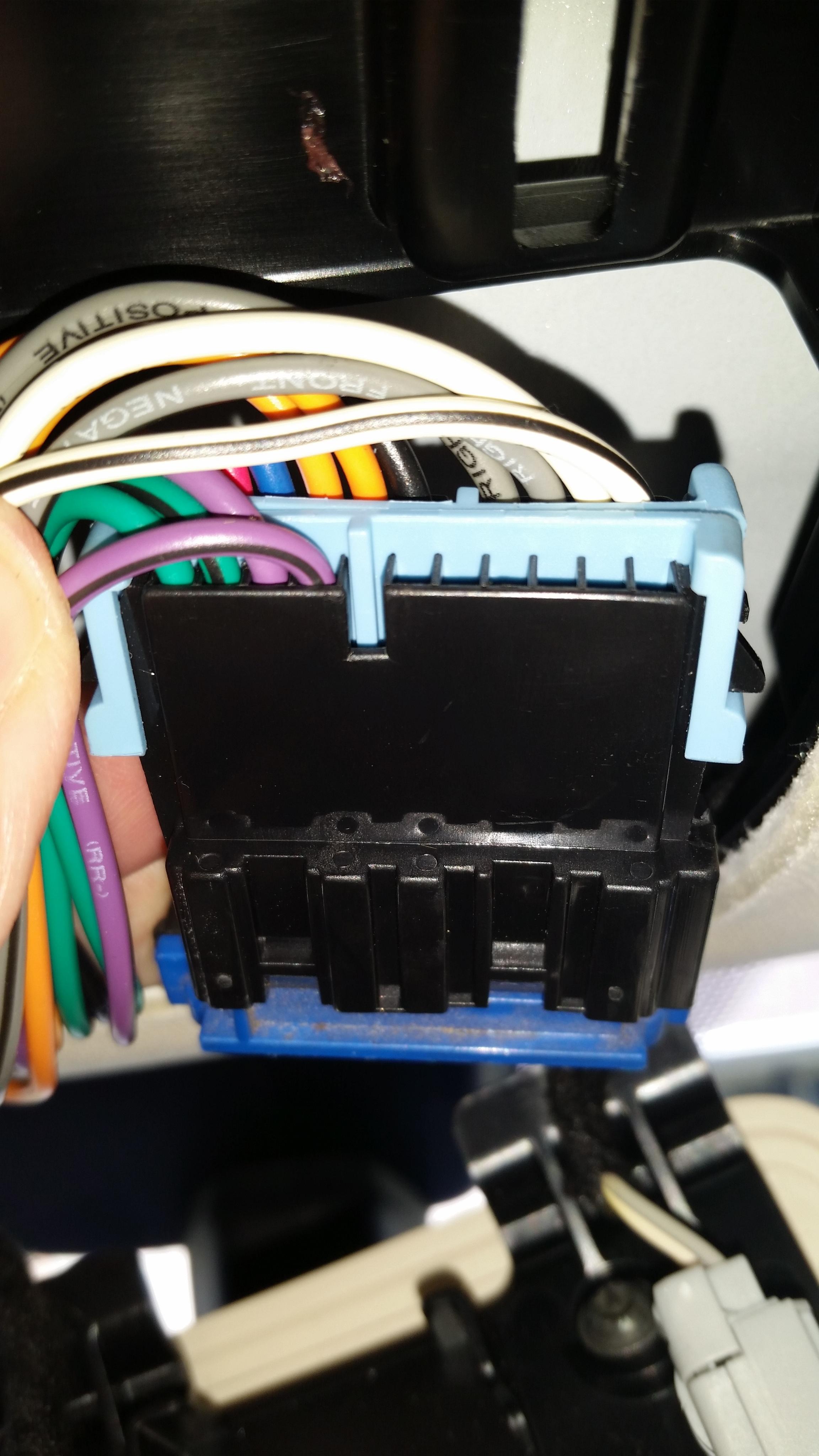 �
�
Jun 21, 2015
EK123 Constant power from dash - PA66?
<<
When I open up my speaker grill in my headliner, I did not find a small connector.
>>
Ran front/back coax today, drilled small hole as many have described. Thank you all.
I was planning on getting power from the obd port. But I found I have this connector behind the microphone grill.
p85D, VIN 78XXX, delivered april 2015. Small connector as pictured. Looks to me like it may say PA66? Anyone know where I can get the connector to make a short fused power cord? other suggestions?
thanks
e
 �
�
Aug 30, 2015
mscott I have this same connector on my MS built mid-July 2015 (VIN 96XXX). I took my voltmeter to it today and this doesn't appear to have a 12V supply on it. I measured about 10.1V between the black and green wire, but it was not a constant 10.1V. On AC, my meter showed about 250mV of ripple, which I can't really explain. (Maybe my 20-year-old meter is on the fritz?) The 10V was there even when I turned the car off, but because it was a non-standard voltage, I wouldn't feel comfortable running any dash cam from it. There's no telling if even that 10.1V supply would be able to provide any meaningful level of current or what might be affected if you tried.
There was about 300mV between the black and white wires, as well as between the green and white wires. I wonder what Tesla has in mind for this little plug?
Of course, I'd love for somebody to prove me wrong, as I'm hoping to wire up a BlackVue-650 over Labor Day weekend. :wink:�
Aug 30, 2015
Nosken I found the kind at Frys Newer VIN constant 12v power options (dashcam)? - Page 4
http://www.frys.com/product/3582124�
Aug 30, 2015
mscott Doh! I guess I wasn't making contact with the third wire when I checked it. After reading the other thread Nosken mentioned, I went back and checked again. Sure enough, there's 13.5V there on the outer two wires. Sweet!�
Sep 30, 2015
FlatSix911 Good information - I will have to check my 085xxx build to see if the connector is present.�
Oct 29, 2015
hpjtv The 2 USB ports have always on power (it might not be the case for older models, mine is a Dec 2014). So you can charge your phones/tablets even when you are not in the vehicle. The 12V outlet is switched off when the car is off. I haven't tried this yet but since the USB is always on, there's got to be a DC-DC converter that's always on that you should be able to tap 12V from.�
Oct 29, 2015
HankLloydRight Or just use the OBDII port for always-on 12V power.�
Nov 23, 2015
MsElectric Is Tesla continuing to make available the "always on" 12V source in the rearview mirror area for 2014 December+ Model S vehicles all the way up to recently produced vehicles? When did they start offering the "spare" 12V source in that area?
I really hope they continue to offer the spare always on 12V source available so that dash cam installations do not require complicated methods to tap into vehicle power.�
Không có nhận xét nào:
Đăng nhận xét